
Propeller shaft
- Make
- Land Rover
- Model
- Discovery II
- Section
- OVERHAUL › Propeller shaft
PROPELLER SHAFTS
OVERHAUL
47-9
OVERHAUL
Propeller shaft
$% 47.15.11
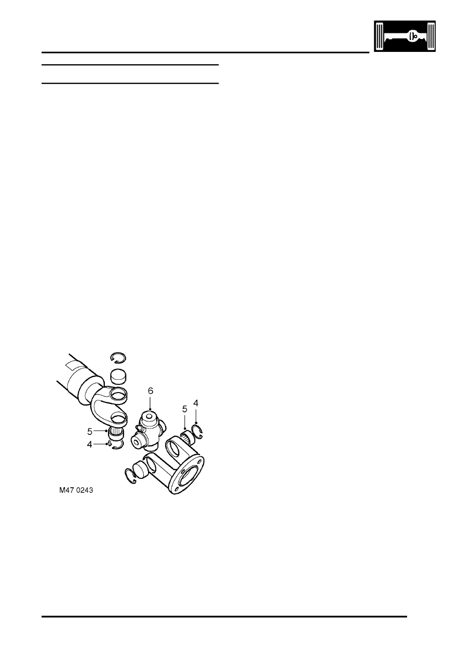
The following bearing replacement procedure
applies to the universal joints of both the front and
rear propeller shafts, including the Hookes joint (i.e.
double universal joint) of the front propeller shaft.
Disassembly
1. Remove propeller shaft:
l
For front propeller shaft.
l
2. Thoroughly examine the universal joint for
signs of damage or wear.
3. Clean the universal joint bearing cups and
circlips.
CAUTION: Before removal, mark the
position of the spider pin relative to the
journal yoke ears on the propeller shaft
joint. This will ensure correct assembly and
reduce the possibility of imbalance.
4. Remove the circlips.
5. Tap the yokes to eject bearing cups. Remove
bearing cups.
6. Remove spider from yokes.
7. Clean yokes and bearing cup locations.
Reassembly
1. Remove bearing cups from new spider.
2. Check all needle rollers are present and
correctly positioned in bearing cups.
3. Enter new spider, with seals, into one of the
yokes.
4. Partially insert one bearing cup into yoke and
enter spider trunnion into bearing cup.
5. Insert opposite bearing cup in yoke.
6. Press both cups into place.
7. Press each cup into its respective location in
yoke up to lower land of circlip groove. Damage
may be caused to cups and seals if cups
pass this point.
8. Fit circlips and check no end float exists.
9. Engage spider in second yoke. Fit bearing cups
and circlips as described in steps 4 to 8.
10. Fit propeller shaft:
l
l
Parts & tools for this job Staging For Land Rover Discovery
- TOOLTorque wrenchSearch: 3/8 inch torque wrench
- TOOLSocket setSearch: socket set metric
- BOOKHaynes manualSearch: Haynes manual Land Rover Discovery
Links open Amazon search results in a new tab. As an Amazon Associate I earn from qualifying purchases.