
LIFTING
- Make
- Land Rover
- Model
- Discovery II
- Section
- LIFTING
LIFTING AND TOWING
08-1
LIFTING AND TOWING
LIFTING
The following instructions must be carried out before
raising the vehicle off the ground.
l
Use a solid level ground surface.
l
Apply hand brake.
l
Select 'P' (Automatic gearbox) or 1st gear
(Manual gearbox) in main gearbox.
l
Select Low range in transfer gearbox.
To avoid damage occurring to the under body
components of the vehicle the following jacking
procedures must be adhered to.
DO NOT POSITION JACKS OR AXLE STANDS
UNDER THE FOLLOWING COMPONENTS:
l
Body structure
l
Bumpers
l
Fuel lines
l
Brake lines
l
Front radius arms
l
Panhard rod
l
Steering linkage
l
Rear trailing arms
l
Fuel tank
l
Engine sump
l
Gearbox bell housing
Vehicle jack
The jack provided with the vehicle is only intended for
use in an emergency, for changing a tyre. DO NOT
use the jack for any other purpose. Refer to Owner's
Handbook for vehicle jack location points and
procedure. Never work under a vehicle supported
solely by the vehicle jack.
Hydraulic jack
A hydraulic jack with a minimum 1500 kg, 3,300 lbs
load capacity must be used. Do not commence
work on the underside of the vehicle until
suitable axle stands have been positioned under
the axle.
WARNING: Always chock the wheels when
jacking. The hand brake acts on the
transmission, not the rear wheels, and may be
ineffective when the wheels are off the ground.
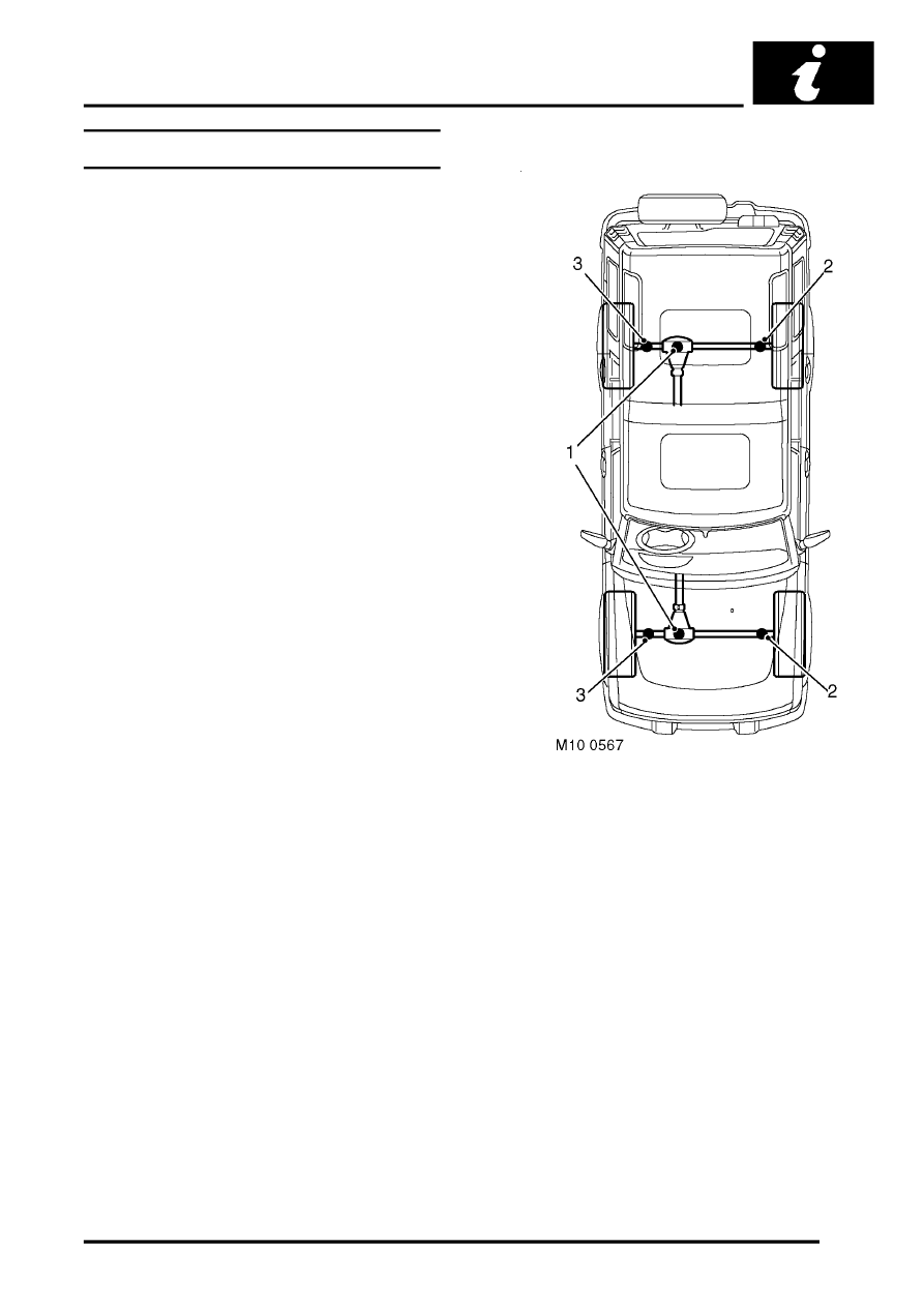
Raising and supporting the vehicle
Position cup of hydraulic arm under differential
casing (1).The differential casing is not central to
the axle. Care should be taken when raising the
front road wheels off the ground as the rear axle
has less sway stiffness.
Raise vehicle to enable an axle stand to be installed
under left hand axle tube (2).
Position an axle stand under right hand axle tube (4).
Carefully lower jack until vehicle sits securely on both
axle stands, remove jack.
Alternatively, the axle stands can be positioned
under the chassis longitudinals at the front and/or
rear of the vehicle.
Parts & tools for this job Staging For Land Rover Discovery
- TOOLTorque wrenchSearch: 3/8 inch torque wrench
- TOOLSocket setSearch: socket set metric
- BOOKHaynes manualSearch: Haynes manual Land Rover Discovery
Links open Amazon search results in a new tab. As an Amazon Associate I earn from qualifying purchases.