
REAR AXLE (page 5 of 6)
- Make
- Land Rover
- Model
- Discovery II
REAR AXLE
OVERHAUL
51-13
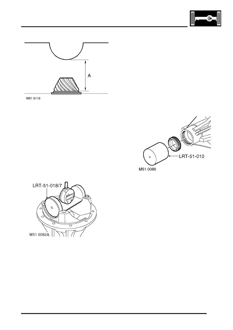
21. Pinion height setting procedure:
l
'A' = Nominal pinion height setting, 74.390.
l
'B' = Setting block height.
l
'C' = Head height setting.
l
'C' = 'A' - 'B'. Subtract nominal pinion height
'A' from setting block height 'B' (on side of
setting block).
l
Example: 74.390 - 73.130 = 1.26 mm
(2.929' - 2.88' = 0.049'). Therefore pinion
head height reading is 1.260 mm
±
0.025
mm (0.049'
±
0.001').
CAUTION: Setting block height must be
checked using figures on side of block.
22. Align setting gauge LRT-51-018/7 to setting
block, rock gauge to obtain minimum reading. If
reading is lower than required reading,
decrease shim size. If reading is higher than
required reading, increase shim size.
23. Using LRT-51-003 to restrain pinion flange,
remove bolt and washer. Remove pinion
flange.
24. Remove pinion, collect tail bearing and tail
bearing shim.
25. Remove pinion head bearing outer race and
shim. Discard shim. Ensure bearing race
recess is clean and free from burrs.
26. Fit calculated shim, and using LRT-51-018/4 fit
head bearing outer race.
27. Fit pinion, pinion tail bearing and tail bearing
shim.
28. Fit pinion flange and bolt and washer. Using
LRT-51-003 to restrain pinion flange, tighten
bolt to 100 Nm (74 lbf.ft).
29. Rotate pinion in both directions to settle
bearings.
30. Recheck pinion Torque to Turn, adjust if
necessary.
31. Recheck pinion head height.
32. Using LRT-51-003 to restrain pinion flange,
remove bolt and washer. Remove pinion
flange.
33. Discard bolt.
34. Using LRT-51-010 fit pinion seal.
35. Ensure spacer and tail bearing are correctly
located.
36. Fit pinion, pinion flange and washer.
37. Fit new pinion flange bolt and tighten to 100 Nm
(74 lbf.ft).
38. Lightly oil differential bearings.
39. Ensure spring dowels are fitted in bearing caps.
40. Fit differential bearing outer races and locate
differential assembly into housing.
41. Fit bearing caps and tighten bolts to 10 Nm (7.5
lbf.ft).
Parts & tools for this job Staging For Land Rover Discovery
- PARTRear wheel bearingSearch: Land Rover Discovery rear wheel bearing
- TOOLBearing puller kitSearch: wheel bearing puller kit
- PARTCV boot kitSearch: Land Rover Discovery cv boot kit
Links open Amazon search results in a new tab. As an Amazon Associate I earn from qualifying purchases.