
Description - engine management (ENGINE MANAGEMENT SYSTEM - V8) (page 18 of 43)
- Make
- Land Rover
- Model
- Discovery II (NAS)
- Section
- DESCRIPTION AND OPERATION
ENGINE MANAGEMENT SYSTEM - V8
DESCRIPTION AND OPERATION 18-2-23
Should a malfunction occur, the following fault codes may be evident and can be retrieved by TestBook:
Mass Air Flow (MAF)/ Inlet Air Temperature (IAT) sensor (C0149)
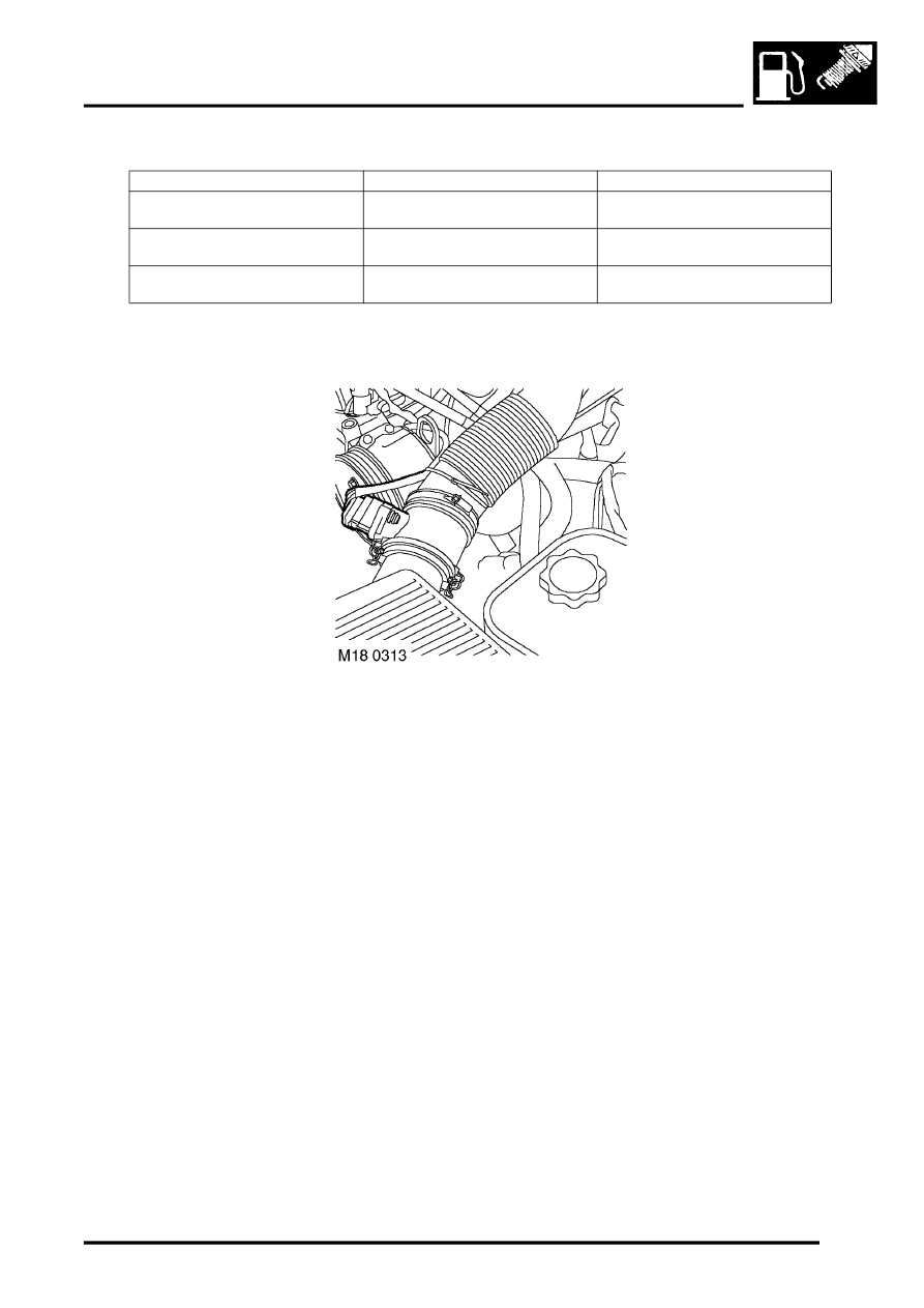
The MAF/ IAT sensors are combined into a single unit and located between the air filter housing and the inlet manifold.
The ECM receives input signals from the MAF/ IAT sensor to calculate the mass of air flowing into the engine inlet
manifold.
Input/Output
The MAF sensor has both electrical input and output. Input to the MAF sensor comes from two different sources.
Battery voltage is supplied to the MAF sensor via fuse 2 of the engine compartment fuse box. The MAF sensor also
utilises a 5 volt reference input via pin 7 of connector C0636 of the ECM. The MAF sensor output voltage is measured
via pin 23 of connector C0636 of the ECM.
The IAT sensor has only electrical output. Output from the IAT sensor is measured at pin 34 of connector C0636 of
the ECM, this is a variable voltage/ resistance measured by the sensor to provide air temperature information to the
ECM.
The MAF/ IAT sensor share the same sensor earth. Sensor earth is via pin 9 of connector C0636 of the ECM.
The MAF/ IAT sensor and its connector has silver plated terminals for its low current signals to protect against
corrosion. DO NOT apply 12V to the 5V supply, as this will destroy the internal circuitry. The MAF/IAT sensor should
not be dropped or roughly handled and should be kept free from contamination.
P code
J2012 description
Land Rover description
P1117
Radiator outlet temperature
thermister low
Thermostat reading below -33
°
C (-
27
°
F)
P1118
Radiator outlet temperature
thermister high
Thermostat reading above 140
°
C
(284
°
F)
P0126
Engine thermostat defective
Difference in radiator and engine
coolant temperatures too small
Parts & tools for this job Staging For Land Rover Discovery
- PARTEngine gasket setSearch: Land Rover Discovery engine gasket set
- TOOLTorque wrenchSearch: 3/8 inch torque wrench
- TOOLFeeler gauge setSearch: feeler gauge set
Links open Amazon search results in a new tab. As an Amazon Associate I earn from qualifying purchases.