
Description - engine management (ENGINE MANAGEMENT SYSTEM - V8) (page 19 of 43)
- Make
- Land Rover
- Model
- Discovery II (NAS)
- Section
- DESCRIPTION AND OPERATION
ENGINE MANAGEMENT SYSTEM - V8
18-2-24 DESCRIPTION AND OPERATION
Mass Air Flow (MAF) Sensor
The MAF sensor utilises a “hot film” element contained in the air intake duct to monitor the mass of the air flow being
drawn into the engine. The MAF sensor contains two sensing elements, one element is controlled at ambient
temperature (e.g. 25
°
C (77
°
F)), while the other is heated to 200
°
C (360
°
F) above the ambient temperature (e.g. 225
°
C
(437
°
F)).
When the intake air passes the heated element, it cools it down, so lowering the resistance of the hot film element. In
order to maintain the same temperature, the circuit to the heated element has to supply more current. The change in
current causes a corresponding change in potential difference to be detected in the monitoring circuit. This change is
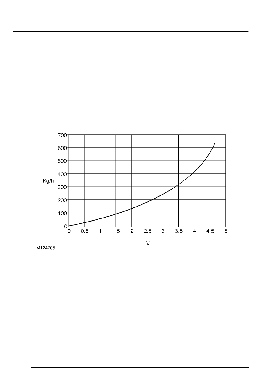
supplied to the ECM as a voltage between 0 and 5V, where it is processed by the ECM's internal mapping to interpret
the data as a measure of the mass of air flow.
The measured air mass flow is used by the ECM to determine the fuel quantity to be injected in order to maintain the
stoiciometric air:fuel mixture for optimum engine performance and low emissions.
Normal operating parameters of the MAF sensor are as follows:
MAF output
If the MAF sensor fails, the ECM implements a back up strategy which is based on throttle angle. Poor throttle
response and reduced performance will result.
The MAF sensor can fail the following ways or supply incorrect signal:
l
Sensor open circuit.
l
Short circuit to vehicle supply.
l
Short circuit to vehicle earth.
l
Contaminated sensor element.
l
Damaged sensor element.
l
Air leak after the MAF sensor.
l
Inlet air restriction.
l
Resistance in wiring harness causing signal offset.
Parts & tools for this job Staging For Land Rover Discovery
- PARTEngine gasket setSearch: Land Rover Discovery engine gasket set
- TOOLTorque wrenchSearch: 3/8 inch torque wrench
- TOOLFeeler gauge setSearch: feeler gauge set
Links open Amazon search results in a new tab. As an Amazon Associate I earn from qualifying purchases.