
Description - engine management (ENGINE MANAGEMENT SYSTEM - V8) (page 23 of 43)
- Make
- Land Rover
- Model
- Discovery II (NAS)
- Section
- DESCRIPTION AND OPERATION
ENGINE MANAGEMENT SYSTEM - V8
18-2-28 DESCRIPTION AND OPERATION
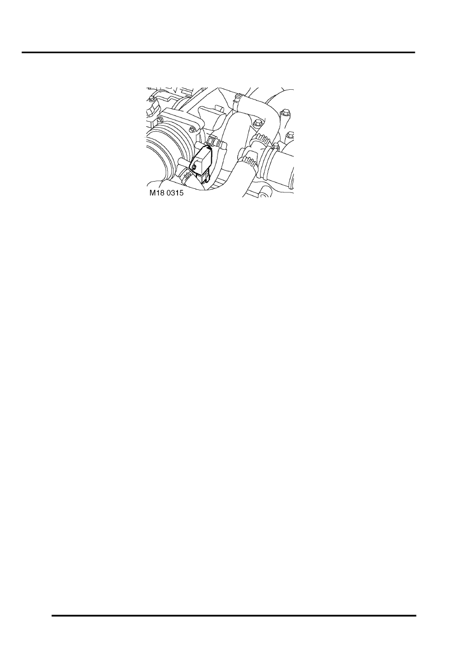
Throttle Position (TP) sensor (C0175)
The TP sensor is located on the throttle body assembly in the engine compartment. The ECM is able to determine the
position of the throttle plate and the rate of change of its angle. The ECM processes the signal received from the TP
sensor.
The TP sensor consists of a resistance track and a sliding contact connected to the throttle plate assembly. As the
throttle is opened and closed the sliding contact moves along the resistance track to change the output voltage of the
sensor. The ECM determines throttle plate position by processing this output voltage. The connection of the sensor
to the throttle plate assembly is via a shaft.
The ECM is able to determine the closed throttle position, this enables the TP sensor to be fitted without the need for
prior adjustment. The TP sensor signal has input into the ECM's fuelling strategy and also to determine closed throttle
position for idle speed control. The TP sensor also supplies the ECM with information to enable the overrun fuel cut
off strategy to be implemented. When the ECM receives closed throttle information from the TP sensor it closes the
injectors for the duration of the closed throttle time.
The TP sensor signal is also used by the Electronic Automatic Transmission (EAT) ECU to determine the correct point
for gear shifts and acceleration kickdown. The ECM also supplies the SLABS ECU with this TP sensor information as
a PWM signal.
Input/Output
The TP sensor has electrical input and output. Input is a 5 volt supply via pin 10 of connector C0636 of the ECM. The
signal output is via pin 24 of connector C0636 and is a varying voltage, less than 0.5V (closed throttle) and greater
than 4.5V (wide open throttle) depending on throttle plate position. The TP sensor earth is via pin 25 of connector
C0636 of the ECM, this acts as a screen to protect the integrity of the TP sensor signal.
The connector and sensor terminals are gold plated for corrosion and temperature resistance, care must be exercised
while probing the connector and sensor terminals.
If the TP sensor signal fails, the ECM uses a default value derived from engine load and speed.
The TP sensor can fail the following ways or supply incorrect signal:
l
Sensor open circuit.
l
Short circuit to vehicle supply.
l
Short circuit to vehicle earth.
l
Signal out of parameters.
l
Blocked air filter (load monitoring, ratio of the TP sensor to air flow).
l
Restriction in air inlet (load monitoring, ratio of the TP sensor to air flow).
l
Vacuum leak
Parts & tools for this job Staging For Land Rover Discovery
- PARTEngine gasket setSearch: Land Rover Discovery engine gasket set
- TOOLTorque wrenchSearch: 3/8 inch torque wrench
- TOOLFeeler gauge setSearch: feeler gauge set
Links open Amazon search results in a new tab. As an Amazon Associate I earn from qualifying purchases.