
Description - engine management (ENGINE MANAGEMENT SYSTEM - V8) (page 14 of 43)
- Make
- Land Rover
- Model
- Discovery II (NAS)
- Section
- DESCRIPTION AND OPERATION
ENGINE MANAGEMENT SYSTEM - V8
DESCRIPTION AND OPERATION 18-2-19
Input/Output
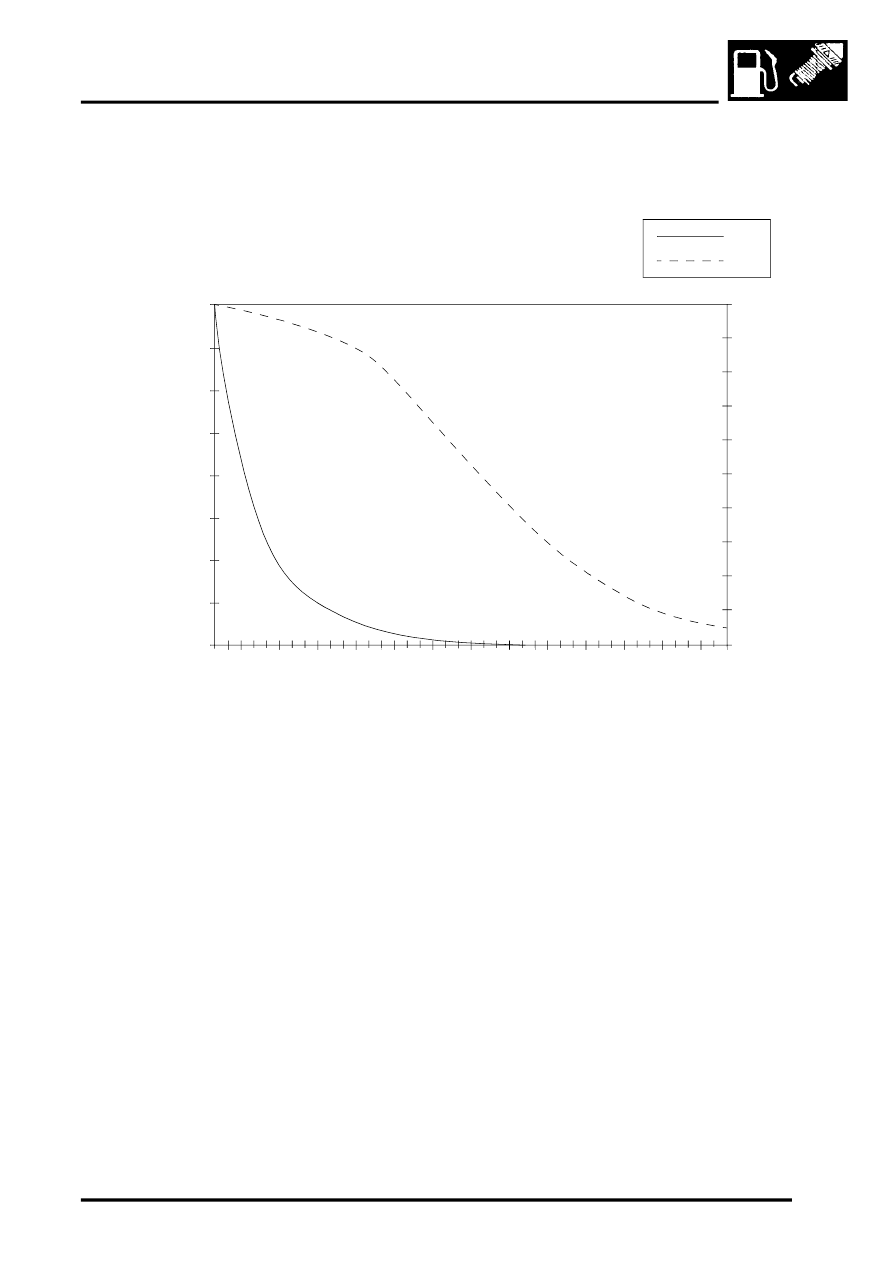
The electrical input and output to and from the ECT sensor are reference voltage and sensor earth. The ECM provides
the ECT sensor with a 5 volt reference via pin 22 of connector C0636 of the ECM, and earth via pin 21 of connector
C0636 of the ECM. The normal operating parameters of the ECT sensor are as follows
Should the sensor fail the ECM has a back up strategy that uses a changing default value during warm up based on
the signal from the inlet air temperature sensor. When the strategy default value reaches 60
°
C (140
°
F), the ECM
implements a fixed default value of 85
°
C (185
°
F). It will also illuminate the MIL.
The ECT sensor can fail the following ways or supply incorrect signal:
l
Sensor open circuit.
l
Short circuit to vehicle supply.
l
Short circuit to earth.
l
Incorrect mechanical fitting.
l
Signal fixed above 40
°
C (140
°
F) will not be detected.
l
Signal fixed below 40
°
C (140
°
F) will be detected.
In the event of an ECT sensor signal failure any of the following symptoms may be observed:
l
Difficult cold start.
l
Difficult hot start.
l
Driveability concern.
l
MIL illuminated.
l
Instrument cluster temperature warning lamp illuminated.
l
Temperature gauge reads excessively hot.
l
Temperature gauge reads excessively cold.
l
Cooling fan will not run.
M124704A
0
20
40
60
80
100
120
140
160
0
0.5
1
1.5
2
2.5
3
3.5
4
4.5
5
V
k
Ω
k
Ω
V
°C
145
-5
0
-35
-2
0
-5
10
25
40
55
70
85
100
11
5
13
0
Parts & tools for this job Staging For Land Rover Discovery
- PARTEngine gasket setSearch: Land Rover Discovery engine gasket set
- TOOLTorque wrenchSearch: 3/8 inch torque wrench
- TOOLFeeler gauge setSearch: feeler gauge set
Links open Amazon search results in a new tab. As an Amazon Associate I earn from qualifying purchases.