
Description - engine management (ENGINE MANAGEMENT SYSTEM - V8) (page 13 of 43)
- Make
- Land Rover
- Model
- Discovery II (NAS)
- Section
- DESCRIPTION AND OPERATION
ENGINE MANAGEMENT SYSTEM - V8
18-2-18 DESCRIPTION AND OPERATION
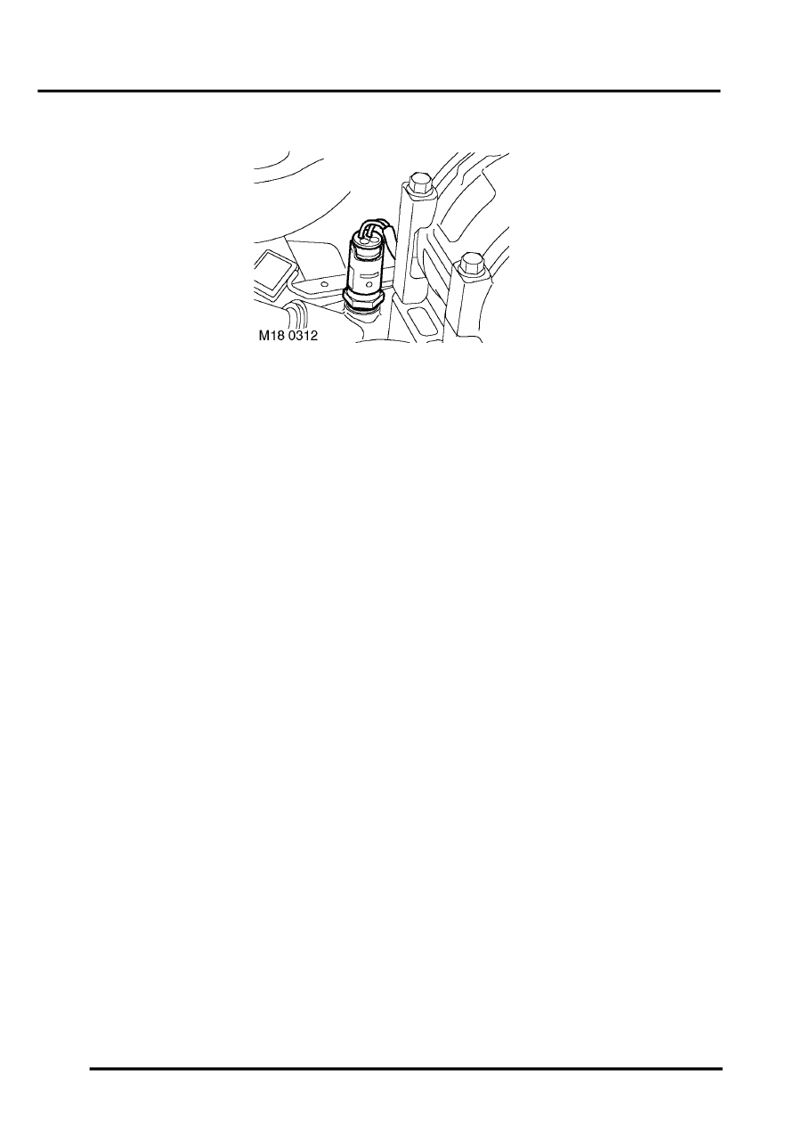
Engine Coolant Temperature (ECT) sensor (C0196)
The ECT sensor is located at the front of the engine adjacent to the coolant outlet pipe. The ECT sensor forms a vital
part of the ECM operating strategy, and therefore the optimum control of the running of the engine. Richer air/ fuel
ratio is required at lower coolant temperatures such as cold starting. Coolant temperature information from the ECT
sensor is also vital to enable the ECM to weaken the air/ fuel mixture as temperature rises to maintain low emissions
and optimum performance.
For NAS vehicles with secondary air injection, the signal from the ECT sensor is monitored at engine start, to
determine whether the conditions are cold enough to warrant secondary air injection to be employed. The ECT sensor
is then monitored to switch off the secondary air injection when the required engine coolant temperature has been
attained.
EMISSION CONTROL - V8, DESCRIPTION AND OPERATION, Secondary Air Injection System.
The ECT works as a Negative Temperature Coefficient (NTC) sensor. As temperature rises, the resistance in the
sensor decreases, as temperature decreases, the resistance in the sensor increases. The ECT sensor forms part of
a voltage divider chain with a pull up resistor within the ECM. Consequently as the ECT sensor resistance changes,
the analogue voltage at the input signal from the ECT sensor to the ECM will be adjusted which corresponds to the
temperature of the engine coolant. With this information, the ECM can implement the correct strategies for cold start,
warm up etc. The ECM supplies the instrument cluster with a pulse width modulated (PWM) coolant temperature
signal to drive the temperature gauge.
Parts & tools for this job Staging For Land Rover Discovery
- PARTEngine gasket setSearch: Land Rover Discovery engine gasket set
- TOOLTorque wrenchSearch: 3/8 inch torque wrench
- TOOLFeeler gauge setSearch: feeler gauge set
Links open Amazon search results in a new tab. As an Amazon Associate I earn from qualifying purchases.