
Description - engine management (ENGINE MANAGEMENT SYSTEM - V8) (page 10 of 43)
- Make
- Land Rover
- Model
- Discovery II (NAS)
- Section
- DESCRIPTION AND OPERATION
ENGINE MANAGEMENT SYSTEM - V8
DESCRIPTION AND OPERATION 18-2-15
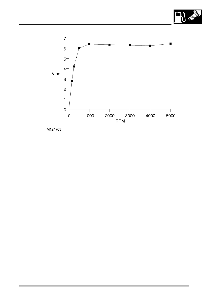
Typical CKP sensor output
The above readings are dependent upon correct air gap between the tip of the CKP sensor and the passing teeth of
the reluctor ring. The correct air gap between the tip of the CKP sensor and the passing teeth of the reluctor ring can
be set by the correct fitting of a spacer as follows:
l
9.2 mm spacer for vehicles with manual gearbox fitted.
l
18 mm spacer for vehicles with automatic gearbox fitted.
It is vital that the correct air gap is maintained, if the air gap becomes too wide the CKP signal becomes too weak,
causing possible engine misfires to occur.
The CKP sensor can fail the following ways or supply incorrect signal:
l
Sensor assembly loose.
l
Incorrect spacer fitted.
l
Sensor open circuit.
l
Sensor short circuit.
l
Incorrect fitting and integrity of the sensor.
l
Water ingress at sensor connector
l
ECM unable to detect the software reference point.
l
Ferrous contamination of crank sensor pin/reluctor
In the event of a CKP sensor signal failure any of the following symptoms may be observed:
l
Engine cranks but fails to start.
l
MIL remains on at all times.
l
Engine misfires (CKP sensor incorrectly fitted).
l
Engine runs roughly or even stalls (CKP sensor incorrectly fitted).
l
Tachometer fails to work.
l
Flywheel adaption reset – ferrous contamination
If the CKP sensor fails while the engine is running the engine will suddenly stall, this is because the CKP sensor has
no backup strategy. If this happens the ECM will produce a fault code that it can store in its memory. If the engine is
not running when the CKP sensor fails, the vehicle will crank but will be unlikely to start, and no fault code will be
generated. In this instance the MIL lamp will remain illuminated and the tachometer will fail to read.
Parts & tools for this job Staging For Land Rover Discovery
- PARTEngine gasket setSearch: Land Rover Discovery engine gasket set
- TOOLTorque wrenchSearch: 3/8 inch torque wrench
- TOOLFeeler gauge setSearch: feeler gauge set
Links open Amazon search results in a new tab. As an Amazon Associate I earn from qualifying purchases.