
Description - engine management (ENGINE MANAGEMENT SYSTEM - V8) (page 9 of 43)
- Make
- Land Rover
- Model
- Discovery II (NAS)
- Section
- DESCRIPTION AND OPERATION
ENGINE MANAGEMENT SYSTEM - V8
18-2-14 DESCRIPTION AND OPERATION
Crankshaft speed and Position (CKP) sensor (C0168)
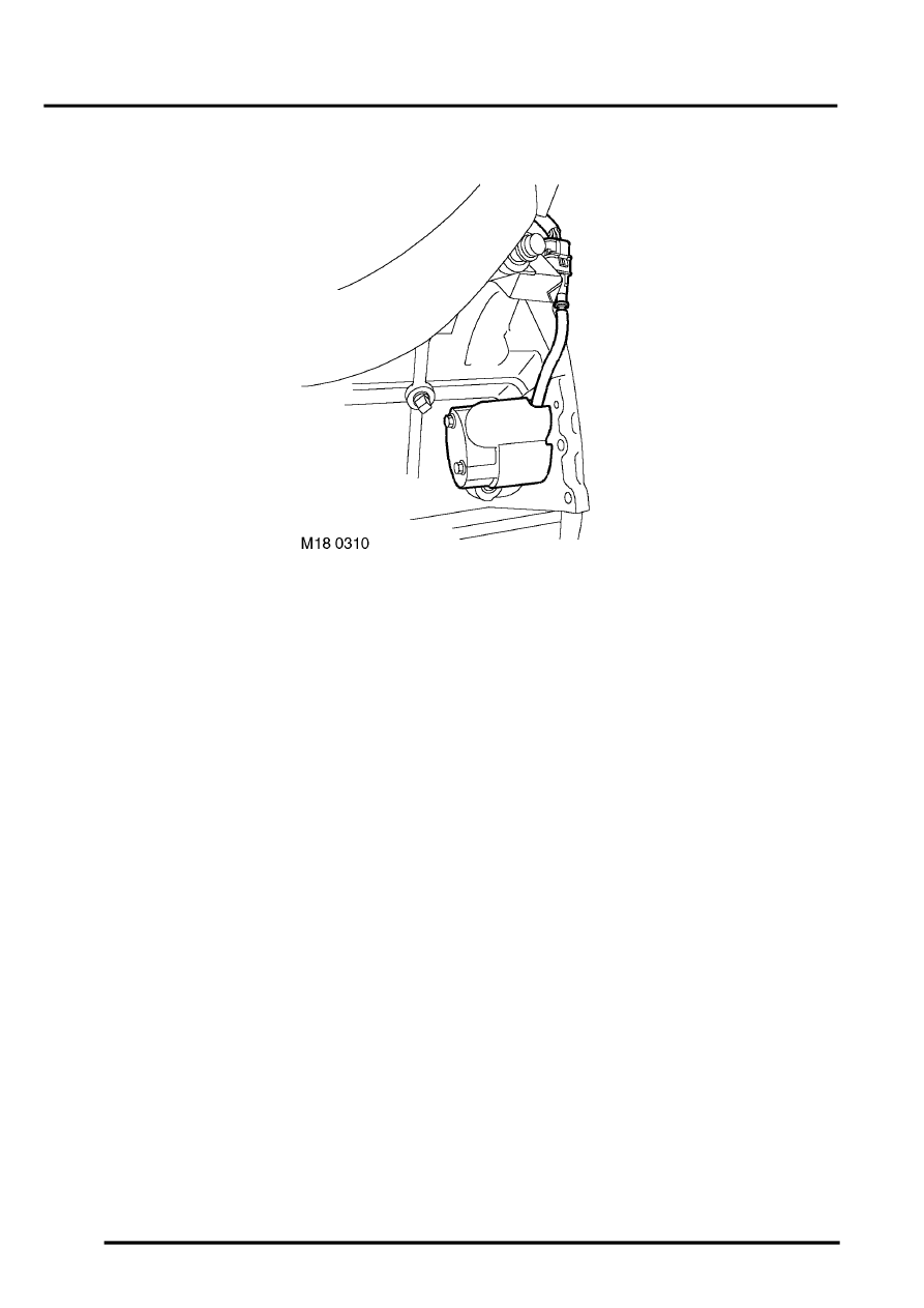
The CKP sensor is located towards the rear of the engine below cylinder number 7, with its tip adjacent to the outer
circumference of the flywheel. The CKP sensor is the most important sensor on the vehicle and without its signal the
engine will not run. The signal produced by the CKP sensor allows the ECM to determine crankshaft angle and speed
of rotation. The ECM uses this information to calculate ignition timing and fuel injection timing.
The CKP sensor works as a variable reluctance sensor. It uses an electromagnet and a reluctor ring to generate a
signal. As the reluctor ring passes the tip of the CKP sensor the magnetic field produced by the sensor is cut and then
re-instated. The ECM measures the signal as an ac voltage.
The output voltage varies in proportion to engine speed. The reluctor ring has a set tooth pattern, 60 teeth are spaced
at 6
°
intervals and are 3
°
wide, two teeth are removed to provide a reference mark at 60
°
BTDC for number 1 cylinder.
There is no back up strategy or limp home facility if this sensor fails, the engine does not run.
Input/Output
Because of the nature of its operation the CKP sensor does not require any electrical input source. The CKP sensor
is a 3 pin variable reluctance sensor generating its own electrical output. The 2 output sources from the sensor are
earthed via pin 46 of connector C0636 of the ECM and sensor output is via pin 32 of connector C0636 of the ECM.
This output is in the form of an ac voltage waveform. The 3rd pin is used by the ECM as an earth screen, this screen
protects the integrity of the CKP sensor signal to ensure that outside electrical interference is eliminated, it is
controlled via pin 45 of connector C0636 of the ECM. The ac voltage generated from the CKP sensor is relative to
engine speed.
Parts & tools for this job Staging For Land Rover Discovery
- PARTEngine gasket setSearch: Land Rover Discovery engine gasket set
- TOOLTorque wrenchSearch: 3/8 inch torque wrench
- TOOLFeeler gauge setSearch: feeler gauge set
Links open Amazon search results in a new tab. As an Amazon Associate I earn from qualifying purchases.