
BRAKES (Description): DESCRIPTION AND OPERATION (page 15 of 15)
- Make
- Land Rover
- Model
- Discovery II
- Section
- DESCRIPTION AND OPERATION
BRAKES
DESCRIPTION AND OPERATION
70-19
ABS sensors
The ABS sensors supply the SLABS ECU with a sinusoidal speed signal from each wheel. An inductive sensor,
installed in the hub bearing of each wheel, senses off a 60 tooth exciter ring integrated into the inner race of the hub
bearing. Each ABS sensor has a fly-lead connecting it to the vehicle wiring.
HDC switch
The HDC switch is a latching push switch installed on the fascia, in the switchpack inboard of the steering wheel.
When pushed in, the switch connects an ignition supply to the SLABS ECU to initiate HDC.
Warning indications
The SLABS ECU operates audible and visual warnings to convey brake system status.
Audible warning
A repetitive chime, at a frequency of 2 Hz, draws attention to warning lamp indications. The chime is produced on the
speaker in the instrument pack.
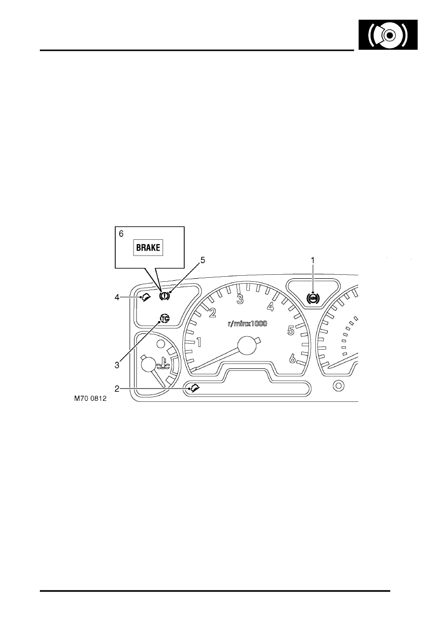
Warning lamps
1 ABS warning lamp
2 HDC fault warning lamp
3 ETC warning lamp
4 HDC information warning lamp
5 Brake warning lamp (all except NAS)
6 Brake warning lamp (NAS only)
The following brake system warning lamps can be found in the instrument pack:
l
A red brake graphic (all except NAS vehicles) or red BRAKE legend (NAS vehicles), to warn of low brake fluid
level, handbrake on and brake control system failure affecting EBD.
l
An amber ABS graphic, to warn of brake control system failure affecting the ABS function.
l
An amber TC graphic, to warn of brake control system failure affecting the ETC function.
l
Two inclined vehicle graphics, one amber (fault) and one green (information), to indicate operating status of HDC
and to warn of brake control system failure affecting the HDC function.
Each warning lamp is illuminated by a separate LED. The ABS, brake and ETC warning lamps are continuously on
while illuminated; the two HDC warning lamps are either continuously on or flash at a frequency of 2 Hz while
illuminated.
Parts & tools for this job Staging For Land Rover Discovery
- PARTBrake padsSearch: Land Rover Discovery brake pads
- TOOLBrake bleeder kitSearch: one man brake bleeder kit
- FLUIDBrake fluidSearch: brake fluid
Links open Amazon search results in a new tab. As an Amazon Associate I earn from qualifying purchases.