
BODY CONTROL UNIT (Description): DESCRIPTION AND OPERATION (page 3 of 18)
- Make
- Land Rover
- Model
- Discovery II
- Section
- DESCRIPTION AND OPERATION
BODY CONTROL UNIT
DESCRIPTION AND OPERATION
86-3-3
BCU outputs
The BCU processes the input signals it receives and uses the information to determine the control outputs that need
to be established for any given set of conditions. The BCU provides controlled outputs for the following systems:
l
Interior courtesy lamps.
l
Fuel flap release actuator.
l
Anti-theft status LED.
l
Engine Control Module.
l
Door lock actuators.
l
Direction indicators and hazard warning lamps.
l
Headlamps.
l
Alarm sounder.
l
Vehicle horns.
l
Battery backed sounder.
l
Starter relay.
l
Passive re-mobilisation exciter coil.
Simultaneous switching of outputs in different units is limited by the bus transfer time, but the skew is no longer than
100 ms for either the BCU or the IDM. When the processor is reset, all outputs are switched off until the inputs have
been read for the first time to check current condition.
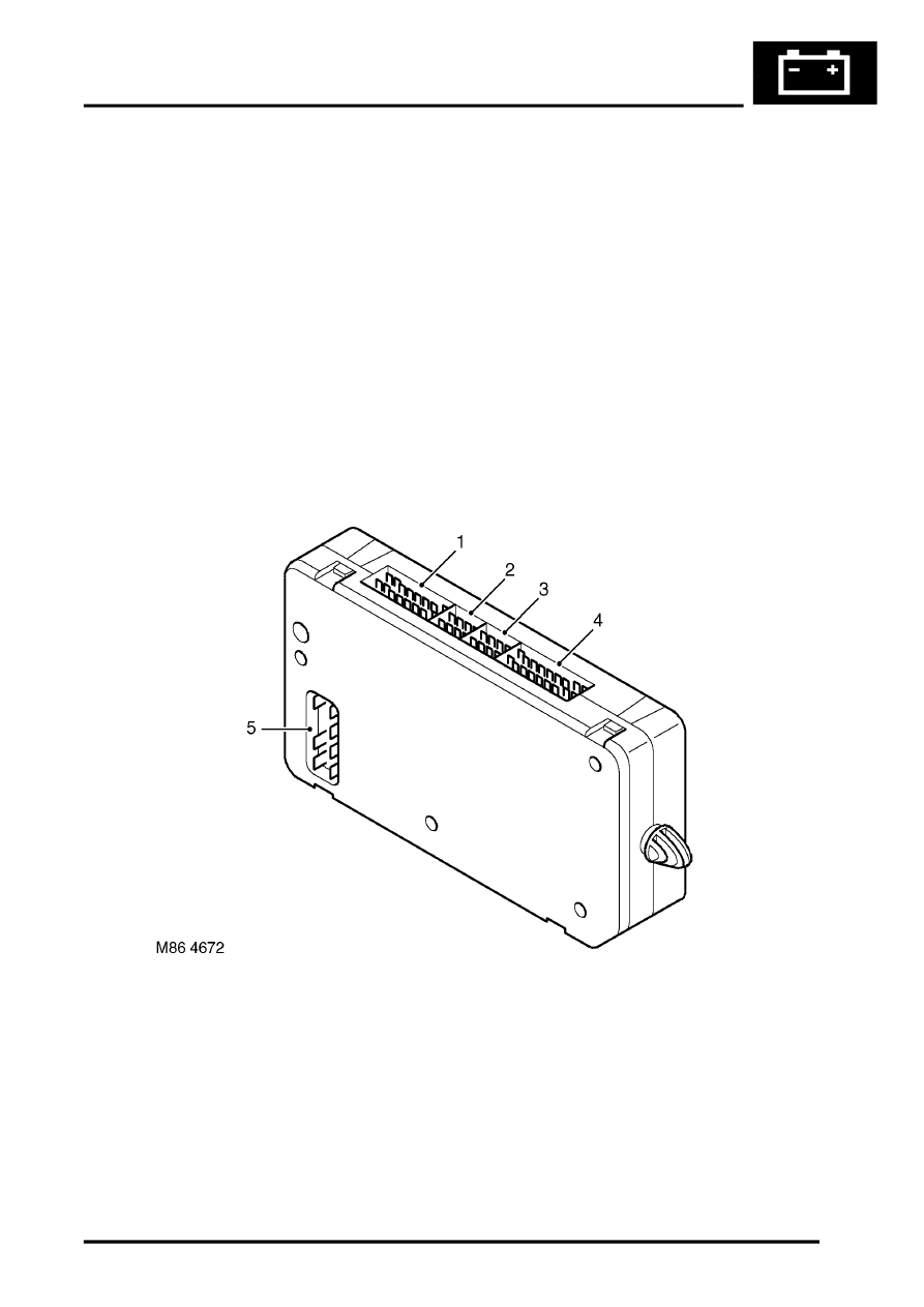
BCU to harness connectors
1 Connector C0661
2 Connector C0662
3 Connector C0663
4 Connector C0660
5 Connector C0664
The pinout details for the BCU connectors are defined below:
Parts & tools for this job Staging For Land Rover Discovery
- TOOLTrim removal tool kitSearch: trim removal tool kit
- PARTTouch-up paintSearch: Land Rover touch up paint
- PARTPanel clip assortmentSearch: Land Rover panel clips assortment
Links open Amazon search results in a new tab. As an Amazon Associate I earn from qualifying purchases.