
AUTOMATIC GEARBOX - ZF4HP22 - 24 (Description): DESCRIPTION AND OPERATION (page 7 of 13)
- Make
- Land Rover
- Model
- Discovery II
- Section
- DESCRIPTION AND OPERATION
AUTOMATIC GEARBOX - ZF4HP22 - 24
44-10
DESCRIPTION AND OPERATION
The lock-up and brake clutches are operated by pressurised transmission fluid from the valve block in the sump. A
manual valve and four solenoid valves, also known as Motorised Valves (MV), control the supply of pressurised
transmission fluid from the valve block:
l
The manual valve controls the supply in P, R, N and D.
l
Solenoid valves MV 1 and MV 2 control the supplies that operate the brake clutches for shift control.
l
Solenoid valve MV 3 controls the supply that operates the lock-up clutch.
l
Solenoid valve MV 4 modulates the pressure of the supplies to the brake clutches, to control shift quality.
Operation of the manual valve is controlled by the selector lever assembly. In the gearbox, a selector shaft engages
with the manual valve. The selector shaft is connected to the selector lever assembly via the selector cable and a
selector lever on the left side of the gearbox. The selector shaft also operates a mechanism that locks the output shaft
when P is selected.
Operation of the solenoid valves is controlled by the EAT ECU.
An output shaft speed sensor in the gearbox housing outputs a signal to the EAT ECU. The EAT ECU compares
output shaft speed with engine speed to determine the engaged gear, and output shaft speed with vehicle speed to
confirm the range selected on the transfer box.
A bayonet lock electrical connector in the gearbox casing, to the rear of the selector lever, connects the solenoid
valves and the output shaft speed sensor to the vehicle wiring.
A pressed steel sump encloses the valve block and collects transmission fluid draining from the gearbox housing. A
suction pipe and filter on the underside of the valve block connect to the inlet side of the fluid pump. A magnet is
installed in the sump to collect any magnetic particles that may be present. A level plug and a drain plug are installed
in the sump for servicing.
Rear extension housing
The rear extension housing provides the interface between the gearbox housing and the transfer box. A splined
extension shaft, secured to the gearbox output shaft by a bolt, transmits the drive from the gearbox to the transfer
box. A seal in the rear of the housing prevents leakage past the extension shaft. A breather pipe, attached to the left
side of the rear extension housing, ventilates the interior of the gearbox and rear extension housings to atmosphere.
The open end of the breather pipe is located in the engine compartment at the right front corner of the engine sump
on gearboxes fitted to early vehicles and is clipped to the top of the gearbox on later vehicles.
Gearbox power flows
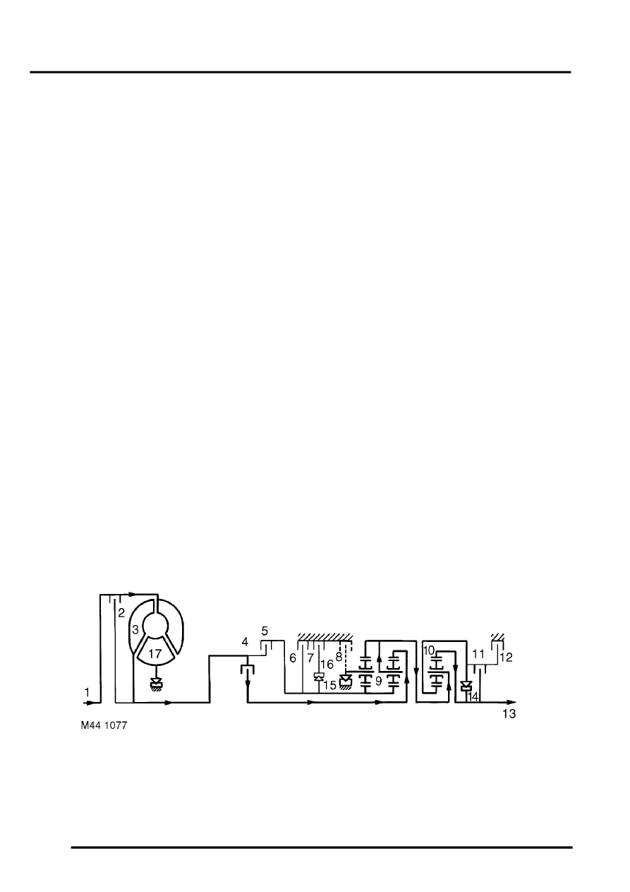
The following Figures show the power flow through the gearbox for each forward gear when D is selected, and for
reverse. The key to the Item numbers on the Figures, and in parenthesis in the accompanying text, can be found on
the 'Sectioned view of gearbox' Figure, above.
1st Gear (D selected)
Clutches (4) and (11) are engaged. The front planet gear carrier of gear set (9) locks against the gearbox housing
through freewheel (15) when the engine powers the vehicle, and freewheels when the vehicle is coasting. Gear set
(10) rotates as a solid unit with the front planet gear carrier. In 1st gear hold brake clutch (8) is applied to provide
overrun braking.
Parts & tools for this job Staging For Land Rover Discovery
- PARTTransmission filter kitSearch: Land Rover Discovery transmission filter kit
- FLUIDAutomatic transmission fluidSearch: Land Rover automatic transmission fluid
- TOOLFluid transfer pumpSearch: fluid transfer pump
Links open Amazon search results in a new tab. As an Amazon Associate I earn from qualifying purchases.