
E7051 Robotized gearbox
- Make
- Alfa Romeo
- Model
- 147 Factory Service Manual
- Year
- 2000–2002
- Section
- Car electronic systems › E7051 Robotized gearbox
E7051 Robotized gearbox
Description
A control system called SELESPEED supervises and governs the operation of the manual gearbox via an electrohydraulic device.
An electronic control unit manages a complex operating logic which enables the gearbox to be used in both 'semi-automatic' conditions, in which the driver manages the engagement of the gears using the lever or the two steering wheel buttons, and automatic 'CITY' mode which delegates gear change management to the electronic system.
The electronic control unit communicates with the engine management control unit via the CAN network and two dedicated lines, one for the engine rpm signal and one for diagnostics.
The control unit drives, by means of a complex operating logic, an electrohydraulic unit located on the gearbox, via a specific electric pump.
For more details, Characteristic of working principle 2127 Hydraulic transmission external linkage .
The supply lines to the control unit and the various system components (sensors and actuators) are protected by two fuses located in the underfacia control unit.
A special maxifuse supplies the system control pump line.
Control unit self-diagnosis notifies of the onset of these faults via a special warning light in the instrument panel: The SELESPEED control unit sends the instrument panel information on the speed engaged. This is shown on the display. For more details, Characteristic of working principle 2127 Hydraulic transmission external linkage .
Description of operation
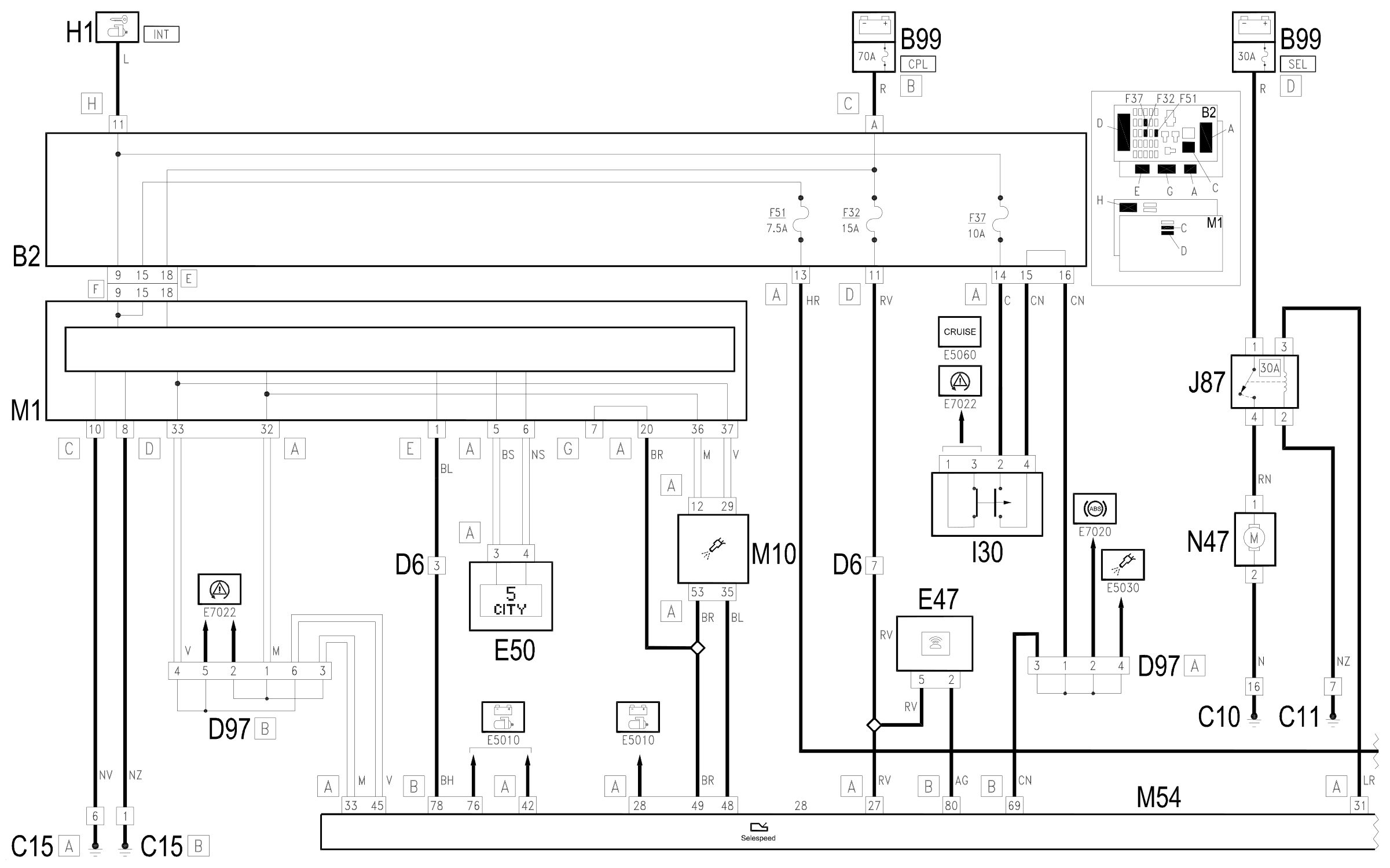
The SELESPEED control unit M54 monitors and controls the entire gearbox management system.
The control unit is supplied by the battery, via the line of the maxifuse CPL llocated on the battery (connector B99 B) and protected by fuse F32 of underfacia control unit B2, at pin 27 of connector A of M54.
The supply controlled by the ignition (15/54) reaches pin 28 of connector A of M54 Wiring diagram E5010 IGNITION AND RECHARGING .
Pins 1 and 2 of connector A of M54 are earthed.
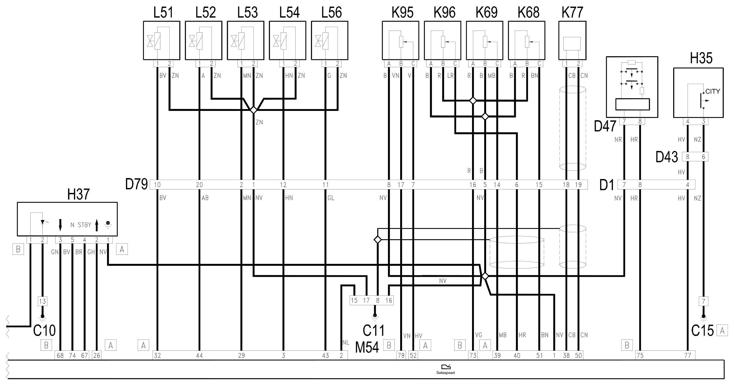
A set of sensors and potentiometers on the gearbox informs the control unit of the engaged gear: the potentiometers are supplied from pin 73 of connector B; the gear selection potentiometer K68 returns a signal to pin 51 of connector A; the gear engagemente potentiometer K69 returns a signal to pin 39 of connector A; the hydraulic unit oil pressure sensor K96 returns a signal to pin 40 of connector A.
The clutch position potentiometer K95 is supplied from pin 79 of connector B and returns a signal to pin 52 of connector A of M54.
Pins 38 and 50 of connector A M54 are connected to the car speed sensor (gearbox input) K77.
The gear control unit H37 is connected to the control unit M54 to indicate a gear shift request: these signals are sent to pins 67, 74, 68 of connector B of M54 from connector A of H37; and pin 26 of connector A.
Connector B of H37 supplies the panel lighting led , which is activated from the line (INT) protected by fuse F51 of underfacia control unit B2.
The CITY mode selection button is located in tunnel switch unit H35 and connected to control unit M54 at pin 77 of connector B.
The steering wheel controls - connected via clock spring contact D47, send signals to pin 75 of connector B of M54.
Pin 69 of connector B of M10 receives the signal coming from the brake lights switch I30, with the supply controlled by the ignition (INT) from fuse F37 of underfacia junction unit B2 ().
In accordance with the operating logic, the control unit controls the electrohydraulic unit located on the gearbox which effects the gear change: the electric pump N47, which keeps the oil in the hydraulic unit under pressure, is controlled from pin 31 of connector A.
The pump N47 is controlled by a specific relay J87 (supplied by the line of the specific maxifuse SEL located on the battery (connector B99 D).
The control unit then controls the opening of the hydraulic unit solenoids:
- the two gear engagement solenoids L51 and L52 are controlled from pins 32 and 44 of connector A of M54;
- the two gear selection solenoids L53 and L54 are controlled from pins 29 and 3 of connector A of M54;
- the clutch control solenoid L56 is controlled from pin 43 3 of connector A of M54.
A safety signal comes from pin 42 of connector A of M54 for the starting enablement relay J5 which gives starting enablement, pin 50 of the starter motor A20; the signal requesting starting reaches pin 76 of connector B Wiring diagram E5010 IGNITION AND RECHARGING .
The control unit M54 also manages the door open buzzer: the driver's door open signal - catch N50 - reaches pin 78 of connector B of M54;
the control for the buzzer E47 leaves pin 80 of connector B.
Self-diagnostic data can be read by connecting the unit to connector G of Body Computer M1 - pin 7: this receives signals from pin 49 of connector A of M54. (the line is shared with the engine control unit M10 via the relevant tester line.
Signals for the gearbox failure warning light in instrument panel E50, and the instrument gear indication display, are sent via the CAN network - pins 33 and 45 of connector A of M54.
The speedometer signal is downloaded via the CAN network.
Pin 48 of connector A is connected to engine management control unit M10, from which it receives an engine rpm signal.
Wiring diagram
Components
| Code | Component | See |
|---|---|---|
| B02 | Junction unit under dashboard | description 5505A |
| B99 | Maxifuse box on battery | description 5530B |
| C10 | Front left earth | |
| C11 | Right front earth | |
| C15 | Facia earth, driver's side | |
| D01 | Front / dashboard coupling | |
| D06 | Front / rear coupling | |
| D43 | Dashboard/centre console coupling | |
| D47 | Clock spring coupling | description 5580C |
| D79 | Selespeed gearbox sensors coupling | |
| D97 | Short circuiting coupling | |
| E47 | Selespeed gearbox buzzer | |
| E50 | Instrument panel | description 5560B |
| H01 | Ignition switch | description 5520A |
| H35 | Switches on tunnel | description 7040L |
| H37 | Gear controls | description 2127A |
| I30 | Brake pedal switch | description 5550D |
| J87 | Selespeed gearbox relay | |
| K68 | Speed selection potentiometer | description 2127E |
| K69 | Gear shift potentiometer | description 2127E |
| K77 | Transmission input speed sensor | description 2127E |
| K95 | Clutch position potentiometer | description 2127E |
| K96 | Pressure sensor on transmission | description 2127E |
| L51 | Solenoid 1 (gear engagement) | description 2127C |
| L52 | Solenoid 2 (gear engagement) | description 2127C |
| L53 | Solenoid 3 (gear engagement) | description 2127C |
| L54 | Solenoid 4 (gear engagement) | description 2127C |
| L56 | Clutch control solenoid | description 2127C |
| M01 | Body computer | description 5505A |
| M10 | Engine management ECU | description 1056B |
| M54 | Selespeed transmission control unit | description 2127E |
| N47 | Selespeed gearbox electric pump | description 2127C |
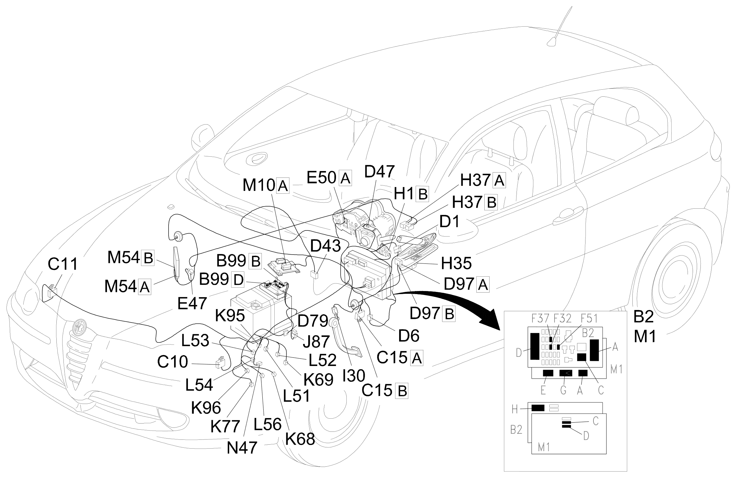
Component location
Parts & tools for this job Staging For 2000 Alfa Romeo 147
- TOOLDigital multimeterSearch: automotive digital multimeter
- PARTAssorted fuse kitSearch: car fuse assortment kit
- TOOLWire crimper and connector kitSearch: wire crimper connector kit
Links open Amazon search results in a new tab. As an Amazon Associate I earn from qualifying purchases.