
E5010 Ignition and recharging
- Make
- Alfa Romeo
- Model
- 147 Factory Service Manual
- Year
- 2000–2002
- Section
- Engine command and control systems › E5010 Ignition and recharging
E5010 Ignition and recharging
Description
The ignition and recharging circuit comprises a battery, starter motor and alternator.
The starter motor consists of a direct current motor supplied by the battery and an excitation solenoid. When the ignition key is turned to the extreme position (AVV), the starter motor windings are supplied, producing electro-magnetic forces which rotate the motor pinion. At the same time, the solenoid is energized and operates the mechanism for engaging the pinion in the flywheel ring gear, thus turning over the engine.
The alternator recharges the battery during normal engine rotation. The alternator shaft (rotor) is turned by the crankshaft by means of a belt. When supplied with an excitation current, the rotor generates a magnetic field that induces an alternating current in the fixed winding (stator). A diode rectifying bridge located on the back of the alternator transforms the alternating current into a direct current, which is sent to recharge the battery.
A voltage regulator, also built into the alternator, maintains a constant voltage supply (about 14V) throughout the load and engine speed ranges.
The efficiency of the recharging system is controlled by the Body Computer, which measures the D+ signal coming from the alternator with the engine running (rpm over 700).
If a fault is detected, the warning light on the instrument panel is lit up.
The Body Computer also acquires the battery voltage in the 6 - 18 V.
The information is then supplied on the CAN network for the controls unit node on the door which excludes some services in the case of a voltage drop (for example Wiring diagram E2510 ROOF LAMP .
Description of operation
When the ignition key in the switch H1 is turned to the extreme position (START) - pin 50 - the winding of the solenoid - pin 50 - of the starter motor A20 is supplied.
This supply comes from the battery via the line of the maxifuse CVM of B99 and fuse F3 of the engine control unit B1.
Pin 30 of A20, the actual starter motor, receives the voltage coming directly from the battery A1.
The direct current generated by the alternator A10 (pin B+) is sent to the battery A1, passing through the motor A20. When the alternator does not turn, and so does not recharge the battery, an earth signal is sent from pin D+ to the Body Computer - pin 19 of connector A: this is connected via the CAN line to the instrument panel E50 and manages, as described above, the switching on of the recharging warning light on the instrument panel E50.
Wiring diagram
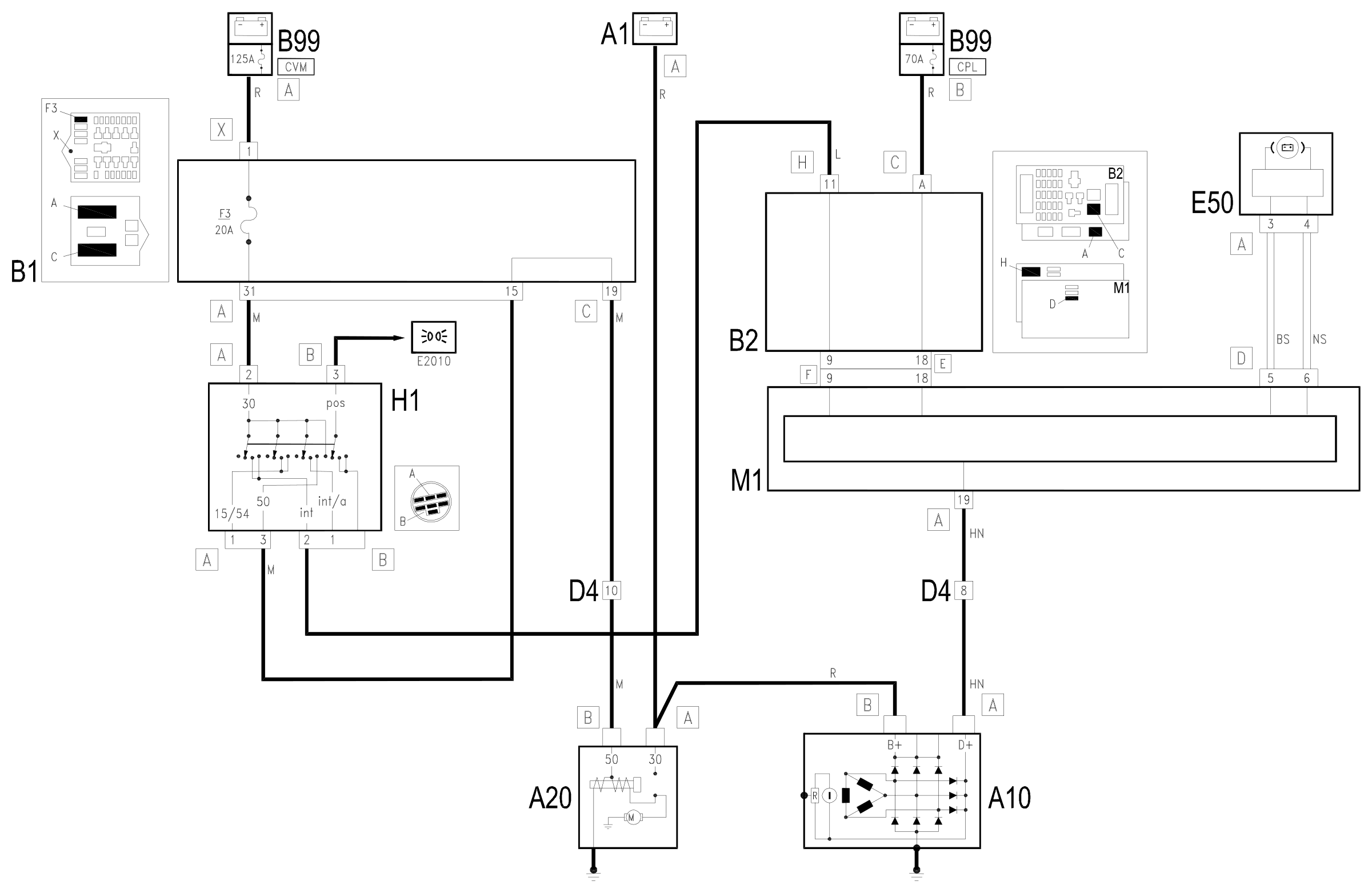
Components
| Code | Component | See |
|---|---|---|
| A01 | Battery | description 5530B |
| A10 | Alternator | description 5530A |
| A20 | Starter motor | description 5520B |
| B01 | Engine compartment junction unit | description 5505A |
| B02 | Junction unit under dashboard | description 5505A |
| B99 | Maxifuse box on battery | description 5530B |
| D04 | Front / engine coupling | |
| E50 | Instrument panel | description 5560B |
| H01 | Ignition switch | description 5520A |
| J05 | Starting enablement relay | |
| M01 | Body computer | description 5505A |
| M54 | Selespeed transmission control unit | description 2127E |
Component location
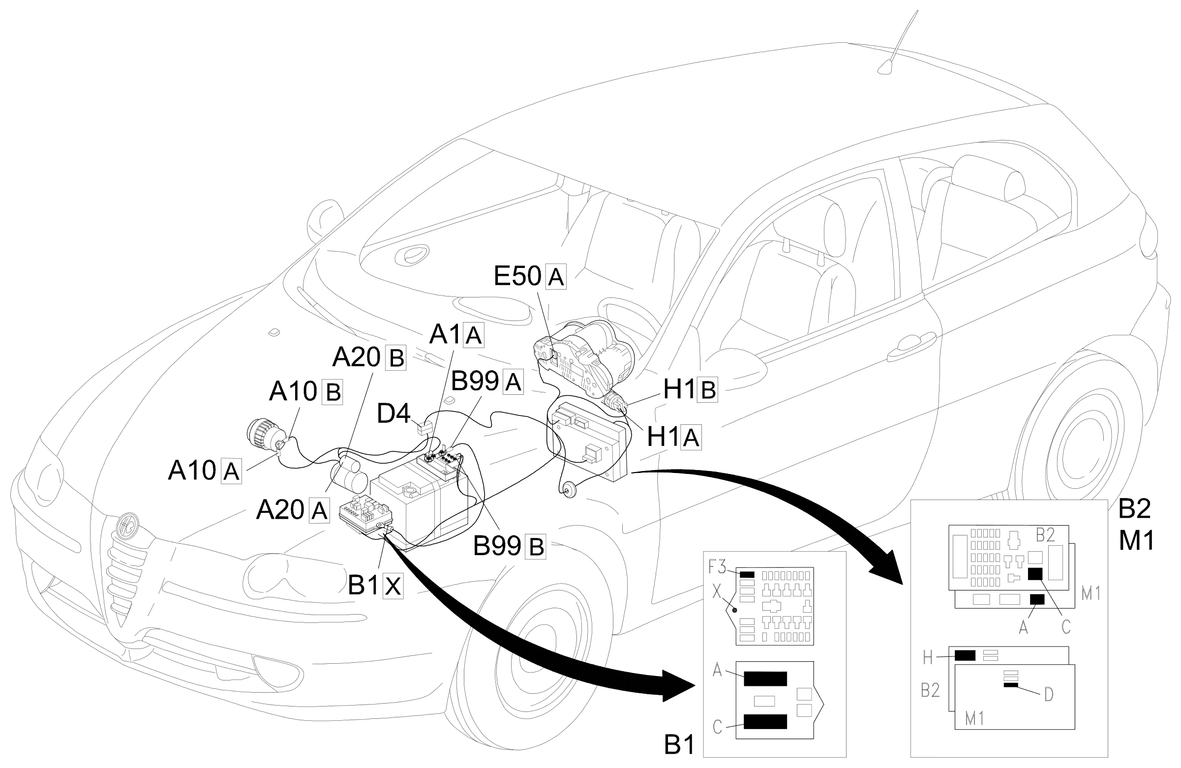
Parts & tools for this job Staging For 2000 Alfa Romeo 147
- PARTEngine gasket setSearch: Alfa Romeo 147 2000 engine gasket set
- TOOLTorque wrenchSearch: 3/8 inch torque wrench
- TOOLFeeler gauge setSearch: feeler gauge set
Links open Amazon search results in a new tab. As an Amazon Associate I earn from qualifying purchases.