
E1010 Power supply
- Make
- Alfa Romeo
- Model
- 147 Factory Service Manual
- Year
- 2000–2002
- Section
- Power supply and ground › E1010 Power supply
E1010 Power supply
Description
The electrical system has been designed with the safety of the vehicle uppermost, to prevent the risk of fire and the other consequences of electrical malfunctions and to reduce defective connections thanks to the adoption of the latest generation connectors.
The distribution of power takes place via the junction units and/or fuse boxes, connected to the control elements (relays and static actuators) in order to ensure the maximum level of electrical protection and the minimum degree of wiring complexity.
The distribution of the functions inside the connectors and the replacement of the connections with short circuit type couplings favours modular arrangements (sub-assembly composition) for all cable looms.
The main safety solutions adopted are:
- supplies protected by maxi fuses to interrupt the electrical system, in the case of a short circuit, just downstream of the battery (see detail below);
- the only cables without maxi fuses (starter motor and alternator) are protected and positioned in a safe place;
- the layout of the entire system is designed to optimize the risk of damage in the case of a failure or accident;
- the routing of the actual cables has been optimized, reducing incorrect positioning and noise due to vibrations;
- all the cables are highly resistant to abrasions
- there are special cables in the engine compartment which are resistant to high temperatures and protected with outer casings or pipes;
- the cables in the passenger compartment are protected by corrugated pipes and plush type bands to reduce noise
- the main connections are fitted with anti-slip devices on the terminals (secondary lock) and safety closures (lever lock) to prevent any distortion of the terminals.
All the electrical systems are supplied by the battery at a voltage of 12. V.
The battery is, in turn, recharged by the alternator Wiring diagram E5010 IGNITION AND RECHARGING during engine operation.
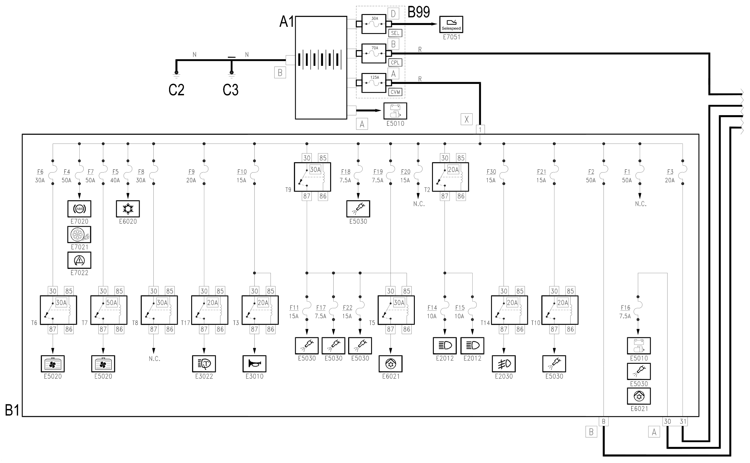
The main supply lines are protected by maxifuses, grouped together in a box directly on the positive battery terminal and connected directly to it.
The box contains the following maxifuses, named according to the circuits protected:
- CVM: engine compartment junction unit supply
- CPL: underdashboard junction unit supply
- SEL: SELESPEED Wiring diagram E7051 ROBOTIZED GEARBOX robotized gearbox supply.
Some circuits are supplied continuously, even if the vehicle is stopped and the ignition is off, as they are connected directly to the battery.
Other circuits are supplied by turning the ignition key to various different positions:
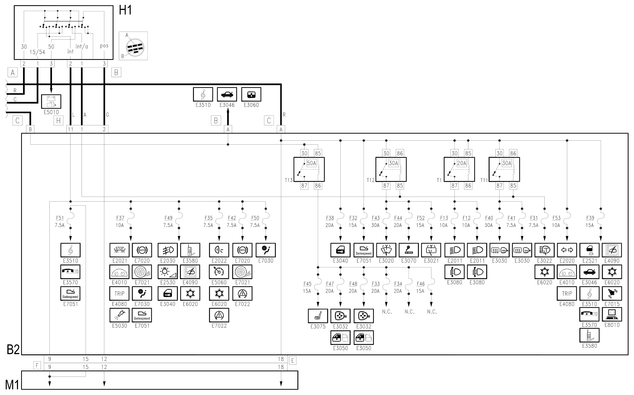
- when the key is inserted and turned to the first click, the ignition is turned on (ON position) and several circuits are supplied, which are thus called 'ignition-operated' (lines 'INT' and '15/54');
- the second click - AVV position - instead supplies the starter motor (line '50')., disconnecting some circuits (those which absorb most power), thus ensuring the maximum flow of current to the starter motor; ('INT/A' line).
- on the other hand, by extracting the key and turning it in the opposite direction (and pressing the special button) the PARK position is engaged which supplies the side lights even with the key switched off ('POS' line) Wiring diagram E2010 SIDE LIGHTS / NUMBER PLATE
Note
The lines through which the supply is distributed to the various electrical devices are shown on the wiring diagrams relating to the various functions and systems.
This general diagram shows all the lines which depart from the battery and the MAXIFUSE boxes; reference should be made to the specific diagrams for greater detail.
Description of operation
All the electrical equipment and systems are supplied by the battery A1.
The main supply lines are protected by the MAXIFUSE box B99 which contains the fuses named according to the circuits protected:
- CVM: engine compartment junction unit supply B1, at connector X;
- CPL: underdashboard junction unit supply B2, at pin A of connector C;
- SEL: SELESPEED Wiring diagram E7051 ROBOTIZED GEARBOX robotized gearbox supply.
Other circuits are supplied by turning ignition key H1 to various different positions:
- in the ON position, numerous circuits and services controlled by the ignition (INT line) are supplied ('INT' and '15/54' lines): pin 2 of connector B and 1 of connector A;
- in the AVV position - the starter motor is supplied; (line '50') Wiring diagram E5010 IGNITION AND RECHARGING ; in this position several circuits are disconnected ('INT/A' line): 1 of connector B;
- in the PARK position the side lights are supplied ('POS' line); 3 of connector B;
Wiring diagram
Components
| Code | Component | See |
|---|---|---|
| A01 | Battery | description 5530B |
| B01 | Engine compartment junction unit | description 5505A |
| B02 | Junction unit under dashboard | description 5505A |
| B99 | Maxifuse box on battery | description 5530B |
| C02 | Battery earth on engine | |
| C03 | Battery earth on bodyshell | |
| H01 | Ignition switch | description 5520A |
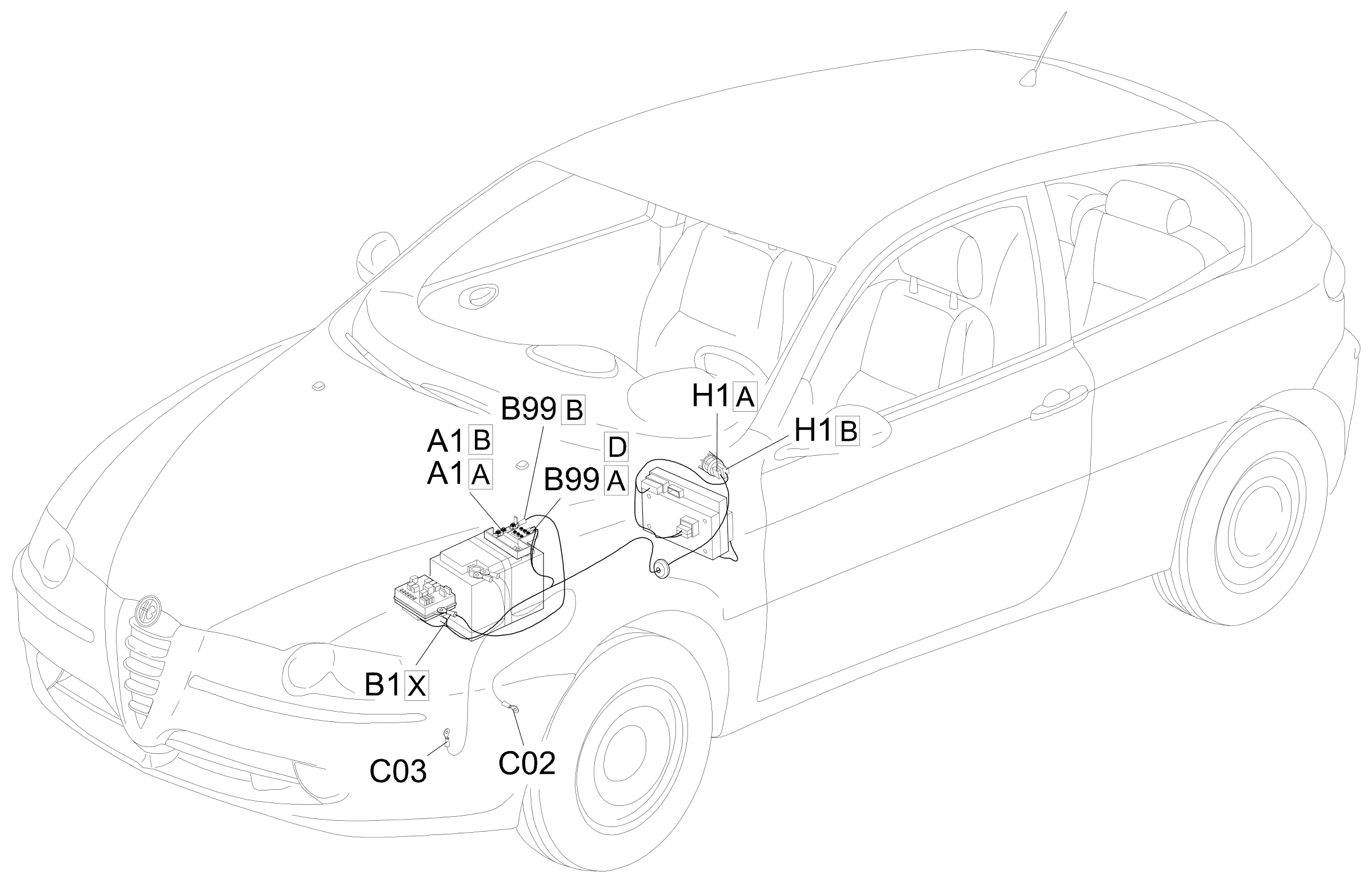
Component location
Parts & tools for this job Staging For 2000 Alfa Romeo 147
- TOOLDigital multimeterSearch: automotive digital multimeter
- PARTAssorted fuse kitSearch: car fuse assortment kit
- TOOLWire crimper and connector kitSearch: wire crimper connector kit
Links open Amazon search results in a new tab. As an Amazon Associate I earn from qualifying purchases.