
Electronic control
- Make
- Alfa Romeo
- Model
- 147 Factory Service Manual
- Year
- 2000–2002
- Section
- Hydraulic transmission external linkage › Electronic control
Electronic control
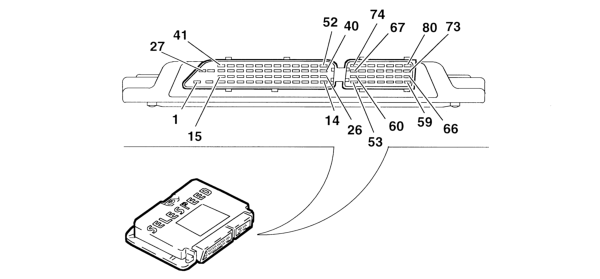
- 1 Earth
- 2 Earth
- 3 EV4 gear + selection actuator solenoid
- from 4 to 25 - Not connected
- 26 Gear selection bit 0
- 27 Power source (+30)
- 28 Ignition-operated power source
- 29 On-off solenoid EV3 controlling selection actuator
- 30 Not connected
- 31 Pump relay feed
- 32 Solenoid EV1 controlling engagement actuator
- 33 CAN L line
- 34 Not connected
- 35 Not connected
- 36 Car speed
- 37 Not connected
- 38 Gearbox input rpm sensor +
- 39 Gear engagement position sensor
- 40 Pressure sensor
- 41 Not connected
- 42 Ignition relay control
- 43 Solenoid EV0 controlling clutch actuator +
- 44 Solenoid EV2 controlling gear engagement actuator +
- 45 CAN H line
- 46 Not connected
- 47 Not connected
- 48 Engine rpm
- 49 Tester line K
- 50 Gear input rpm sensor -
- 51 Gear selection position sensor
- 52 Clutch position sensor
- from 53 to 66 - Not connected
- 67 Speed selection bit 1
- 68 Speed selection bit 3
- 69 Brake pedal switch
- 70 Not connected
- 71 Not connected
- 72 Display data control output
- 73 Gear engagement position sensor power source
- 74 Speed selection bit 2
- 75 Speed selection bit 4
- 76 Ignition signal (+50)
- 77 CITY switch
- 78 Door button
- 79 Clutch position sensor power source (+5V)
- 80 Buzzer output control
It is fitted in the passenger compartment under the dashboard on the passenger side.
The CFC 208F control unit communicates with the injection control unit through a CAN line and is fitted with a tester line.
PIN OUT
The control unit performs the task of:
receiving signals from the various sensors;
interfacing with the injection control unit (via the CAN C line);
controlling the hydraulic system;
interfacing with the instrument panel (via the CAN line);
managing the buzzer.
The control unit uses the following signals for the management of these strategies:
engine rpm (from the injection control unit via the CAN C line);
transmission input rpm sensor;
clutch position sensor;
selection position sensor;
shift position sensor;
accelerator pedal potentiometer/motorised throttle (from injection control unit via CAN C line);
vehicle speed (from ABS via CAN C line);
ignition key;
driver's door switch;
brake pedal switch;
hydraulic unit fluid pressure.
Parts & tools for this job Staging For 2000 Alfa Romeo 147
- TOOLTorque wrenchSearch: 3/8 inch torque wrench
- TOOLSocket setSearch: socket set metric
- BOOKHaynes manualSearch: Haynes manual Alfa Romeo 147
Links open Amazon search results in a new tab. As an Amazon Associate I earn from qualifying purchases.