
WIPERS AND WASHERS (Description): DESCRIPTION AND OPERATION (page 6 of 9)
- Make
- Land Rover
- Model
- Discovery II
- Section
- DESCRIPTION AND OPERATION
WIPERS AND WASHERS
DESCRIPTION AND OPERATION
84-13
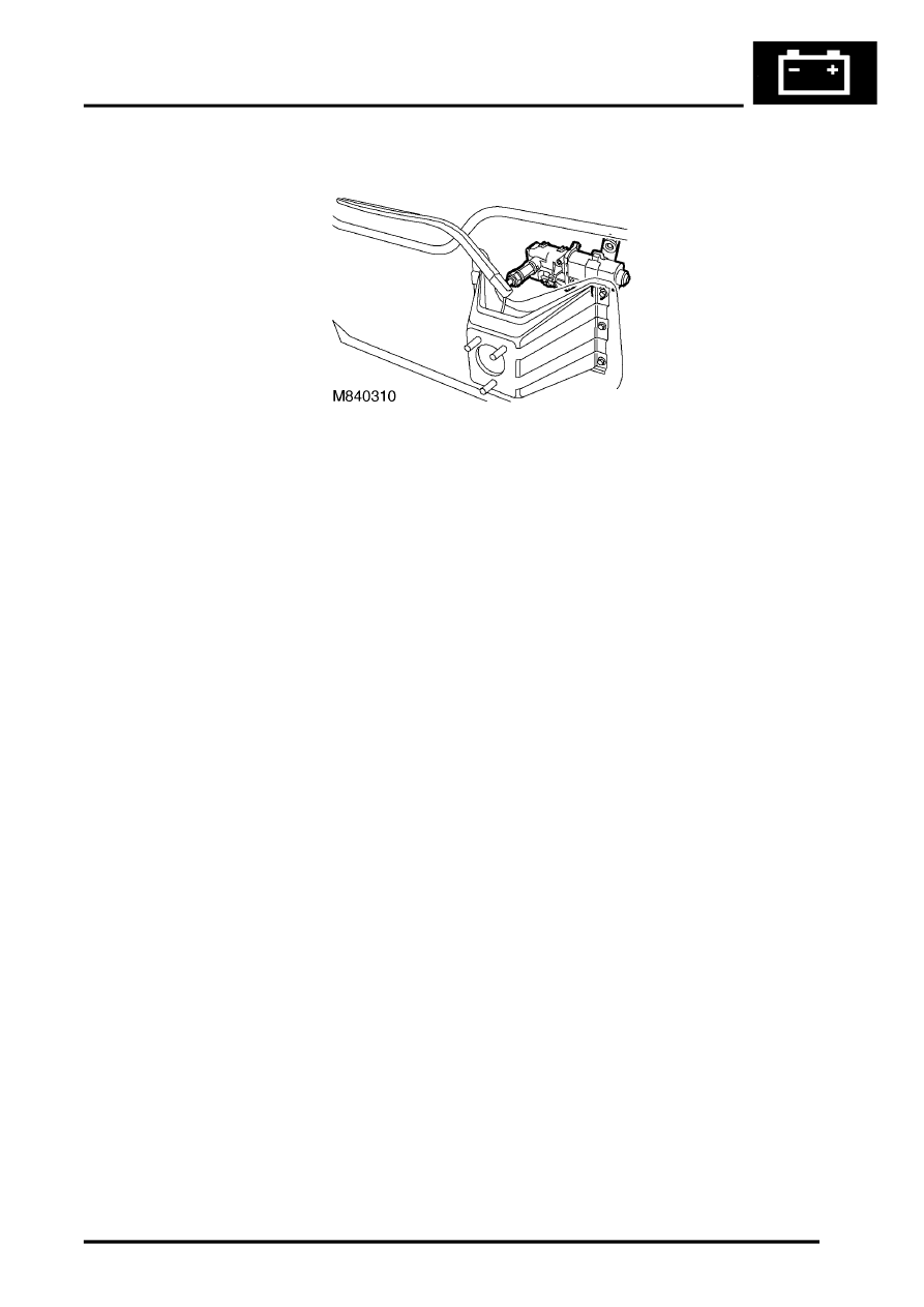
Rear wiper motor
The DC motor contains two permanent magnets and a park switch. An earth braid attached between the motor casing
and the brush pack is utilised to minimise radio interference during wiper functions.
The rear wiper switch provides an earth signal to the BCU, which determines the delay interval, if appropriate. The
BCU then signals the IDM to activate the rear wiper motor relay, which provides power to the rear wiper motor.
To allow the rear wiper to park when the rear wiper is switched off, power flows through the park switch until a cam
in the wiper motor assembly breaks the contact of the park switch. Triggering the park switch grounds the positive
side of the wiper motor causing it to stop abruptly
Washers
The washer system comprises a reservoir, washer pumps, hoses and washer jets. The front washers are controlled
from a stalk switch on the steering column and the rear washers are operated by a non-latching pushbutton switch on
the fascia adjacent to the instrument pack.
Reservoir
The reservoir is located behind the front bumper in the inner wheel arch and has a capacity of 6.0 litres (12.5 US pints).
A filler neck tube is connected to the reservoir with a seal and extends into the engine compartment on the front left
hand side. The filler neck tube contains a removable filter to prevent particle contamination and a yellow float to show
reservoir contents. The washer filler neck tube is sealed with a cap which is coloured blue for identification.
Two electric washer pumps are located on the rear face of the reservoir and supply washer fluid to the front
windscreen and the tail door window. Each pump is sealed to the reservoir with a rubber sealing grommet.
On vehicles with headlamp powerwash fitted, a third pump is fitted with a sealing grommet to the front face of the
reservoir.
The reservoir and filler neck tube are manufactured from moulded opaque nylon. The reservoir has moulded lugs for
attachment to the vehicle body. A bracket is attached to the top of the filler neck tube and locates in a hole in the body
to secure the top of the tube.
Front screen washer jets
Two washer jets for the front windscreen are fitted to the top surface of the bonnet and held in place with plastic clips.
Each washer jet is connected via a hose to an in-line valve. The in-line valve prevents the washer fluid draining back
to the reservoir and ensures that the washers operate immediately the washer pump is operated. From each in-line
valve the washers are connected via a short hose to a 'T' connector. From the 'T' connector a single hose connects
to the outlet of the front washer pump. Each jet has two jets which can be adjusted to allow full fluid coverage of the
windscreen.
Parts & tools for this job Staging For Land Rover Discovery
- PARTWiper bladesSearch: Land Rover Discovery wiper blades
- PARTWasher pumpSearch: Land Rover Discovery washer pump
Links open Amazon search results in a new tab. As an Amazon Associate I earn from qualifying purchases.