
STEERING (Description): DESCRIPTION AND OPERATION (page 8 of 11)
- Make
- Land Rover
- Model
- Discovery II
- Section
- DESCRIPTION AND OPERATION
STEERING
57-12
DESCRIPTION AND OPERATION
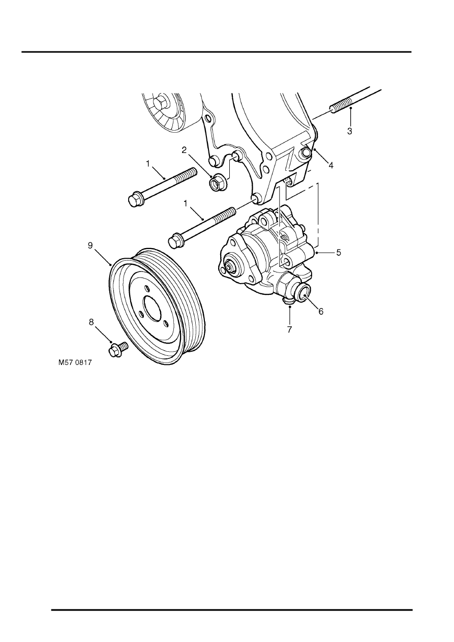
PAS pump - V8
1 Bolt 2 off
2 Nut
3 Stud
4 Auxiliary housing
5 PAS pump
6 Outlet
7 Inlet
8 Bolt 3 off
9 Drive pulley
The PAS pump is located on the auxiliary housing and is attached by two bolts, the bolts go through flanged bushes
in the auxiliary housing. A stud passes through the PAS pump and through a flanged bush in the auxiliary housing,
the auxiliary housing and PAS pump are secured by a nut. As the two bolts and nut are tightened the bushes move
slightly and the flange of each bush clamps the PAS pump. A drive pulley is attached to the pump drive shaft with
three bolts, and is belt driven at a ratio of 1.4 crankshaft revolutions to 1 of the drive pulley. Fluid is drawn into the
PAS pump inlet from the reservoir through a flexible hose at low (suction) pressure. Fluid at high pressure from the
PAS pump outlet is supplied to the rotary control valve on the steering box.
The PAS pump is a roller vane type and has an internal pressure regulator and flow control valve. The roller vanes
can move in slots in the pumps rotor and are moved outwards by centrifugal force as the pump rotates. The pump
rotor rotates in the pump housing, the internal shape of the housing forms a 'cam' shape. Due to the 'cam' shape the
volume of the housing decreases between the inlet and outlet ports.
As the pump rotor rotates towards the pump inlet the volume between the roller vanes and the pump housing
increases, this action causes a depression in the chamber between the pump roller vanes and the housing. As the
rotation continues the chamber is opened to the pump inlet, and the depression in the chamber causes fluid to be
drawn in. The roller vanes continue past the inlet port, closing off the inlet port and trapping the fluid in the chamber
between the rollers and the pump housing.
Parts & tools for this job Staging For Land Rover Discovery
- TOOLTie rod end toolSearch: tie rod end puller
- TOOLBall joint separatorSearch: ball joint separator
- FLUIDPower steering fluidSearch: Land Rover power steering fluid
Links open Amazon search results in a new tab. As an Amazon Associate I earn from qualifying purchases.