
Description - SRS (RESTRAINT SYSTEMS) (page 6 of 6)
- Make
- Land Rover
- Model
- Discovery II
- Section
- DESCRIPTION AND OPERATION
RESTRAINT SYSTEMS
75-8
DESCRIPTION AND OPERATION
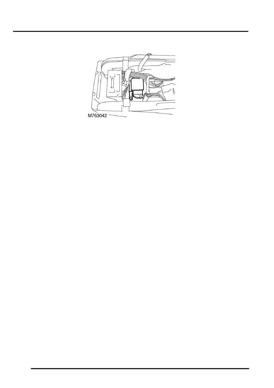
Diagnostic and Control Unit (DCU)
The SRS DCU is an electronic single point crash sensor. It is capable of sensing if a crash has taken place. If all the
relevant parameters are met, then the DCU deploys the airbag(s) and seat belt pretensioners.
The DCU is bolted to the transmission tunnel beneath the centre console in the area of the handbrake.
The DCU performs the following functions:
l
Internal self test, system monitoring and fault detection.
l
SRS warning lamp operation.
l
System deployment.
Self test, system monitoring and fault detection
The DCU performs a self-test during start-up and then continually during operation of the system. The following
components are tested:
l
The decelerometer.
l
The electromechanical safing sensor.
l
The microprocessor.
l
The continuity of squib ignition circuits.
l
The SRS warning lamp.
If the DCU detects a fault, it stores the fault code in memory. Diagnose the DCU with TestBook. The DCU cannot
be serviced. It must be replaced if it is faulty.
SRS warning lamp operation
The DCU controls the SRS warning lamp contained in the instrument cluster.
System deployment
The DCU determines when the system deploys based on inputs from both the decelerometer and the
electromechanical safing sensor. Both are located within the DCU. Neither are serviceable.
The electromechanical safing sensor uses a magnet and ball bearing system to provide a mechanical confirmation of
vehicle deceleration. The ball bearing is held in place by the magnet. The strength of the magnet is calibrated such
that the force required for the ball bearing to move away from the magnet will only occur if the vehicle decelerates
suddenly, as in an accident.
The SRS deploys only if both the decelerometer reading and the safing sensor operation occur at the same time.
Parts & tools for this job Staging For Land Rover Discovery
- TOOLOBD2 scanner with SRSSearch: OBD2 scanner ABS SRS
- TOOLTrim removal tool kitSearch: trim removal tool kit
Links open Amazon search results in a new tab. As an Amazon Associate I earn from qualifying purchases.