
Description - SLS (REAR SUSPENSION) (page 7 of 9)
- Make
- Land Rover
- Model
- Discovery II
- Section
- DESCRIPTION AND OPERATION
REAR SUSPENSION
64-18
DESCRIPTION AND OPERATION
When SLS compressor operation is required, the ECU provides a battery supply to energise the SLS relay located in
the engine compartment fusebox. When the relay contacts close, a 12 V supply passes through fusible link 9 in the
engine compartment fusebox, through the relay contacts and operates the air supply unit compressor. The ECU will
then supply power to operate one or both air control valve solenoids and/or the exhaust valve solenoid to inflate or
deflate the air springs as required. The compressor does not need to be powered to deflate the air springs.
The ECU also controls the operation of the SLS audible warning, the SLS warning lamp and the ORM warning lamp.
When the ignition is switched to position II, the ECU performs a three second bulb check and illuminates the SLS and
ORM warning lamps in the instrument pack to check for operation. When the system is operating or a fault is sensed
by the ECU, the ECU will operate the appropriate warning lamp and audible warning as required. The audible warning
is operated by the Body Control Unit (BCU) when it receives a signal from the SLABS ECU. The audible warning is
emitted from a speaker at the rear of the instrument pack.
Depressing the ORM switch for a minimum of 0.5 seconds, completes an earth which the ECU uses as a signal to
initiate the ORM if conditions allow. When the ECU starts ORM, the same earth that was completed by the ORM
switch is pulled to earth by the ECU to activate the ORM warning lamp. The ECU checks for a further operation of the
ORM switch by continuously and very quickly removing the earth for the ORM warning lamp. If the ORM switch is
operated for more than 0.5 seconds, the ECU will detect this and de-activate the ORM.
The SLS part of the SLABS ECU also uses the road speed data generated within the SLABS ECU by the ABS system.
Operation of ORM and extended mode are road speed sensitive and use the ABS signal to monitor the vehicle speed.
When the accessory remote handset is used for the SLS lower and raise functions, the handset transmits RF signals
which are received by the same RF receiver used for the alarm/remote door locking system. The RF receiver passes
this data as a 25 Hz PWM signal to the BCU. The BCU then transmits this data to the SLABS ECU as raise or lower
data. TestBook is required to program the BCU for remote handset operation.
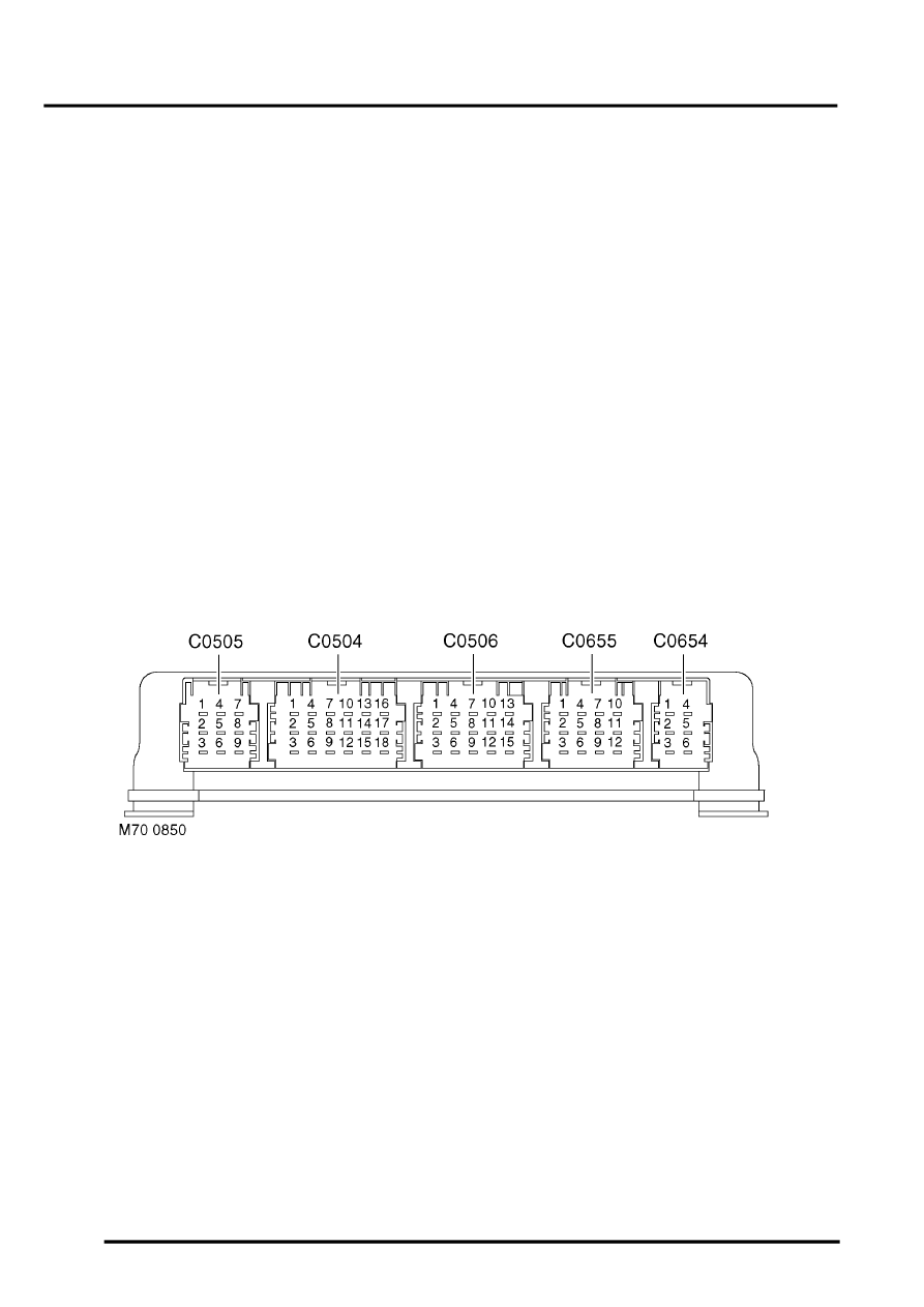
SLABS ECU connector pin details
Parts & tools for this job Staging For Land Rover Discovery
- TOOLCoil spring compressorSearch: coil spring compressor
- TOOLBall joint separatorSearch: ball joint separator
- PARTRear shock absorbersSearch: Land Rover Discovery rear shock absorbers
Links open Amazon search results in a new tab. As an Amazon Associate I earn from qualifying purchases.