
Description - SLS (REAR SUSPENSION) (page 2 of 9)
- Make
- Land Rover
- Model
- Discovery II
- Section
- DESCRIPTION AND OPERATION
REAR SUSPENSION
DESCRIPTION AND OPERATION
64-13
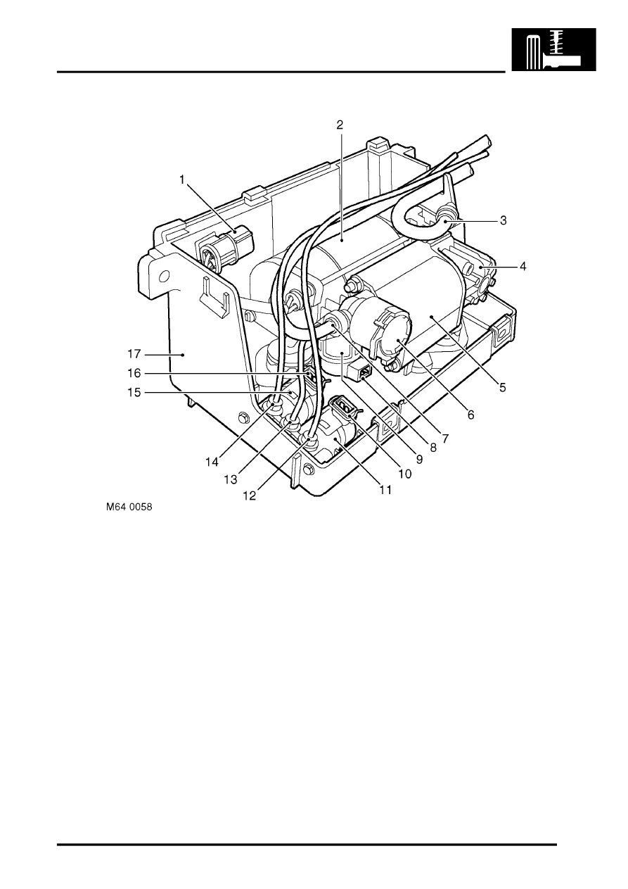
Air supply unit
1 Compressor electrical connector
2 Electric motor
3 Air intake hose
4 Compressor
5 Air dryer
6 Pressure limiting valve
7 Exhaust hose
8 Exhaust valve electrical connector
(black harness connector)
9 Exhaust valve
10 LH air valve electrical connector
(blue harness connector)
11 LH air valve
12 LH air spring supply pipe
13 Air supply/exhaust pipe
14 RH air spring supply pipe
15 RH air valve
16 RH air valve electrical connector
(natural harness connector)
17 Housing
The air supply unit is located in a central position on the outside of the left hand chassis longitudinal. The unit is
contained in a plastic housing attached to the chassis. The housing has a removable lid which is secured with Dzus
fasteners for access to the unit.
The air supply unit comprises a 12 V electric motor, a compressor and air dryer unit, a pressure limiting valve, an
exhaust valve and two air supply control valves. The exhaust and control valves are solenoid operated responding to
signals from the SLABS ECU. The electric motor, compressor, air dryer and pressure limiting and exhaust valve are
mounted on flexible rubber mountings to reduce operating noise.
The electric motor drives a crank with an eccentric pin to which a connecting rod is attached. The connecting rod has
a piston which fits in the bore of the compressor. Operation of the motor rotates the crank, moving the piston in the
bore of the compressor.
Parts & tools for this job Staging For Land Rover Discovery
- TOOLCoil spring compressorSearch: coil spring compressor
- TOOLBall joint separatorSearch: ball joint separator
- PARTRear shock absorbersSearch: Land Rover Discovery rear shock absorbers
Links open Amazon search results in a new tab. As an Amazon Associate I earn from qualifying purchases.