
NAVIGATION SYSTEM (Description): DESCRIPTION AND OPERATION (page 3 of 6)
- Make
- Land Rover
- Model
- Discovery II
- Section
- DESCRIPTION AND OPERATION
NAVIGATION SYSTEM
87-16
DESCRIPTION AND OPERATION
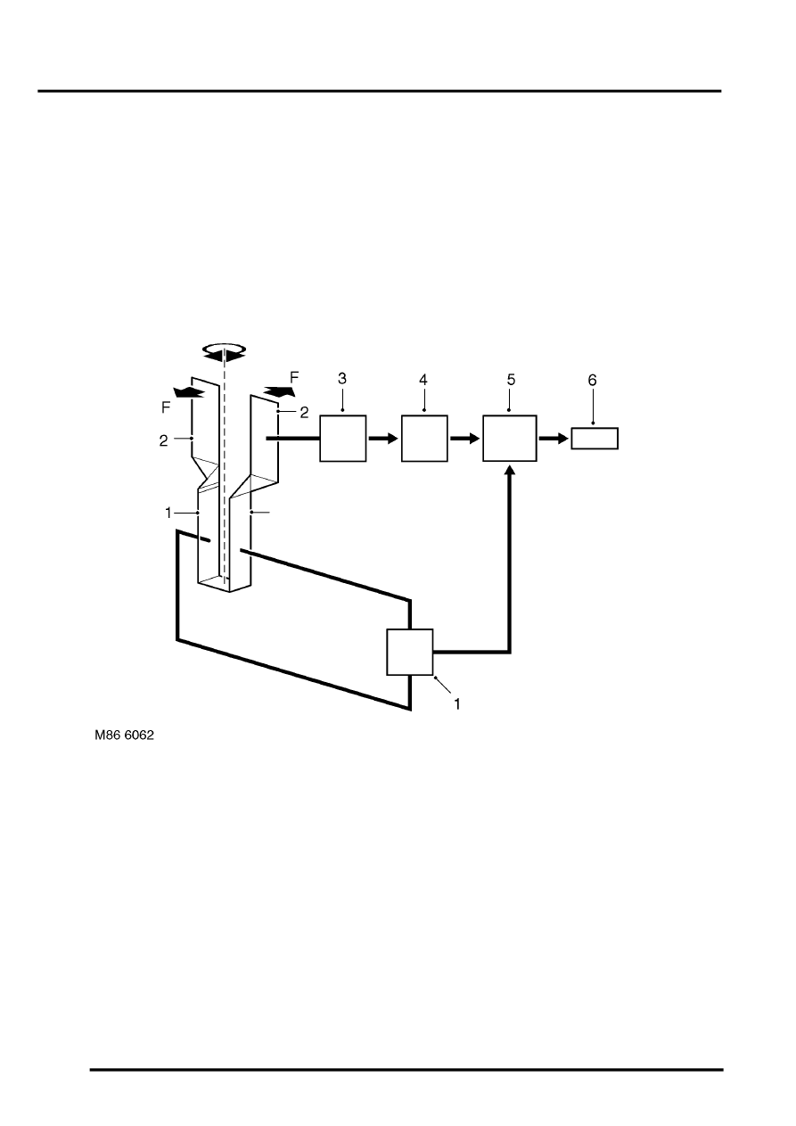
Piezo Gyro Sensor
1 Driver elements
2 Retaining element
3 Amplifier
4 Phase detector
5 Frequency filter
6 Navigation computer
7 Driver stage
The piezo gyro measures the motion of the vehicle around its vertical axis using the Coriolis force. The Coriolis force
is a force which accelerates a body moving away from the rotational axis against the direction of rotation of that axis.
In operation, a mass inside the sensor is excited to a point where it begins to vibrate, similar to a tuning fork. The
vibrations travel perpendicular to the rotational axis and cause continuous potential charge of the mass in relation to
the rotational axis. The forces are measured and converted into a yaw rate to calculate direction.
The sensor is supplied with a current from a driver stage. The current induces vibrations in the driver elements and
retaining elements. As the vehicle turns a corner, the rotational motion is detected by the retaining elements due to
the Coriolis force, and a small electrical voltage is produced.
The voltage is passed to an amplifier and the amplified signal is then passed to a phase detector. The phase detector
establishes the direction of rotation and passes a signal to a frequency filter. Because the gyro sensor is subject to
vibrations produced by means other than cornering, the frequency filter analyses the signals and removes signals not
produced by cornering forces. The filtered signal is passed from the frequency filter to the navigation computer, which
uses it to calculate the direction of travel.
Parts & tools for this job Staging For Land Rover Discovery
- TOOLTorque wrenchSearch: 3/8 inch torque wrench
- TOOLSocket setSearch: socket set metric
- BOOKHaynes manualSearch: Haynes manual Land Rover Discovery
Links open Amazon search results in a new tab. As an Amazon Associate I earn from qualifying purchases.