
HEATING AND VENTILATION (Description): DESCRIPTION AND OPERATION (page 4 of 10)
- Make
- Land Rover
- Model
- Discovery II
- Section
- DESCRIPTION AND OPERATION
HEATING AND VENTILATION
80-6
DESCRIPTION AND OPERATION
Control flaps
Control flaps are installed in the heater assembly to control the temperature and distribution of air. Blend flaps control
the temperature and distribution flaps control the distribution.
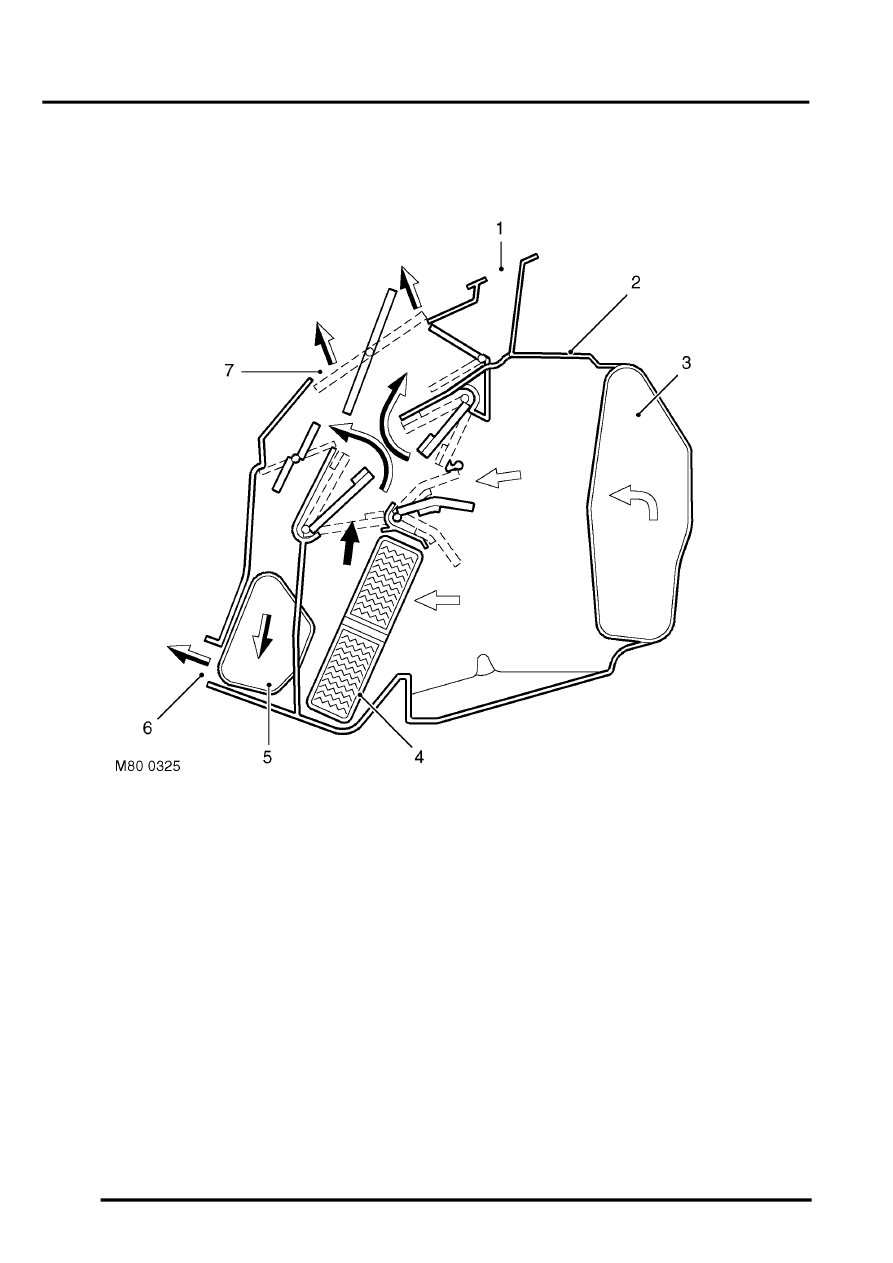
Temperature and distribution control
Figure shows flaps set for medium heat to face level and footwell outlets
1 Windscreen/Side windows outlet
2 Heater assembly casing
3 Air inlet
4 Heater matrix
5 Front footwells outlet
6 Rear footwells outlet
7 Face level outlet
Blend flaps:Two sets of three blend flaps, one LH and one RH, regulate the flow of air through the heater matrix and
a heater matrix bypass, to control the temperature of the air leaving the heater assembly. The two sets of blend flaps
operate independently to allow different temperatures to be set for the LH and RH outlets.
Each blend flap is attached to a spindle. The end of each spindle extends through the side of the heater casing and
is attached to a common lever mechanism on the related side of the casing. A control cable is installed between the
lever mechanism and the related temperature knob on the control panel. When the flow is split between the bypass
and the heater matrix, the two flows mix downstream of the heater matrix to produce an even air temperature at the
individual outlets.
Distribution flaps: Separate distribution flaps are installed to control the flow of air to the footwells, windscreen/side
windows and the LH and RH face level outlets. The distribution flaps are attached to spindles that extend through the
RH side of the heater casing and are attached to a common lever mechanism. A control cable is installed between
the lever mechanism and the distribution knob on the control panel.
Parts & tools for this job Staging For Land Rover Discovery
- TOOLA/C manifold gauge setSearch: AC manifold gauge set
- TOOLUV leak detection kitSearch: AC UV leak detection kit
- PARTCabin filterSearch: Land Rover Discovery cabin filter
Links open Amazon search results in a new tab. As an Amazon Associate I earn from qualifying purchases.