
Piston assemblies (page 2 of 5)
- Make
- Land Rover
- Model
- Discovery II
- Section
- OVERHAUL
ENGINE - V8
12-2-68 OVERHAUL
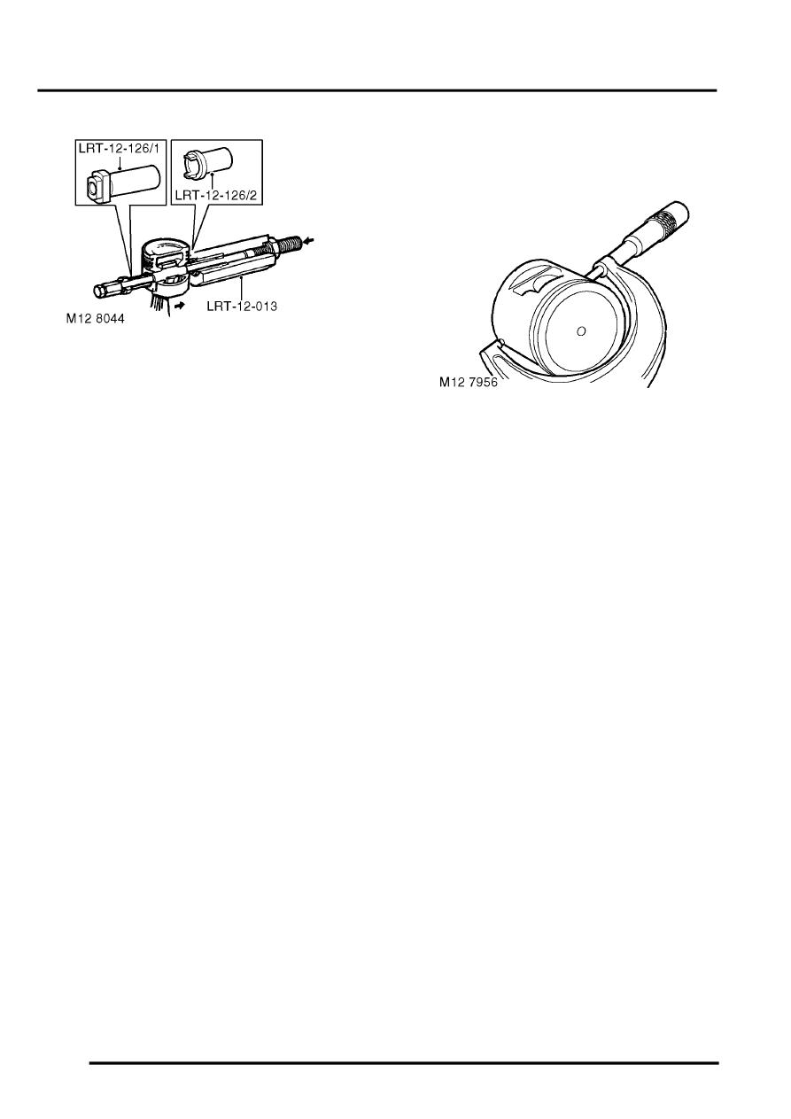
10. Position body of tool LRT-12-013 in vice.
11. Screw large nut back until flush with end of
centre screw.
12. Push centre screw forward until nut contacts
thrust race.
13. Position remover/replacer LRT-12-126/2 in
LRT-12-013 with its long spigot inside bore of
hexagon body.
14. Locate piston and connecting rod assembly on
centre screw and up to remover/replacer
adapter tool LRT-12-126/2.
CAUTION: Ensure that prongs of remover/
replacer adapter LRT-12-162/2 remain in
contact with piston and do not contact
gudgeon pin.
15. Fit remover/replacer bush LRT-12-126/1 on
centre screw with flanged end facing away from
gudgeon pin.
CAUTION: Ensure that remover/replacer
bush LRT-12-126/1 is correctly located in
gudgeon pin bore of piston.
16. Screw stop nut onto centre screw.
17. Lock the stop nut securely with the lock screw.
18. Push connecting rod to locate end of gudgeon
pin in remover/replacer adapter LRT-12-126/2.
19. Ensure remover/replacer bush LRT-12-126/1
is located in gudgeon pin bore of piston.
20. Screw large nut up to tool LRT-12-013.
21. Hold lock screw and turn large nut until
gudgeon pin is withdrawn from piston.
CAUTION: Ensure that prongs of tool LRT-
12–126/2 remain in contact with piston and
do not contact the gudgeon pin.
22. Dismantle tool LRT-12-013 and remove piston,
connecting rod and gudgeon pin.
Inspect
1. Clean carbon from piston. Inspect piston for
distortion, cracks and burning.
2. Remove piston rings from piston.
3. Measure and record piston diameter at 90
°
to
gudgeon pin axis and 10 mm (0.4 in) from
bottom of the skirt. The piston must be 0.015 to
0.045 mm (0.001 to 0.002 in) smaller than the
cylinder bore.
4. Check gudgeon pin bore in piston for signs of
wear and overheating.
5. Pistons fitted on production are graded 'A' or
'B', the grade letter is stamped on the piston
crown.
l
Piston diameter: Grade 'A' = 93.970 to
93.985 mm (3.6996 to 3.7002 in).
l
Piston diameter: Grade 'B' = 93.986 to 94.00
mm (3.7002 to 3.7007 in).
6. Worn cylinders fitted with grade 'A' pistons may
be honed to accept the grade 'B' piston
provided that specified cylinder bore and
ovality limits are maintained. Grade 'B'
pistons are supplied as service
replacements. Do not attempt to de-glaze
cylinder bores.
CAUTION: Ensure replacement pistons are
correct for the compression ratio of the
engine. The compression ratio will be found
on the cylinder block adjacent to the engine
serial number.
7. Check gudgeon pins for signs of wear and
overheating.
8. Check clearance of gudgeon pin in piston.
l
Gudgeon pin to piston clearance = 0.006 to
0.015 mm (0.0002 to 0.0006 in).
Parts & tools for this job Staging For Land Rover Discovery
- PARTEngine gasket setSearch: Land Rover Discovery engine gasket set
- TOOLTorque wrenchSearch: 3/8 inch torque wrench
- TOOLFeeler gauge setSearch: feeler gauge set
Links open Amazon search results in a new tab. As an Amazon Associate I earn from qualifying purchases.