
Description - engine management (ENGINE MANAGEMENT SYSTEM - V8) (page 37 of 43)
- Make
- Land Rover
- Model
- Discovery II (NAS)
- Section
- DESCRIPTION AND OPERATION
ENGINE MANAGEMENT SYSTEM - V8
18-2-42 DESCRIPTION AND OPERATION
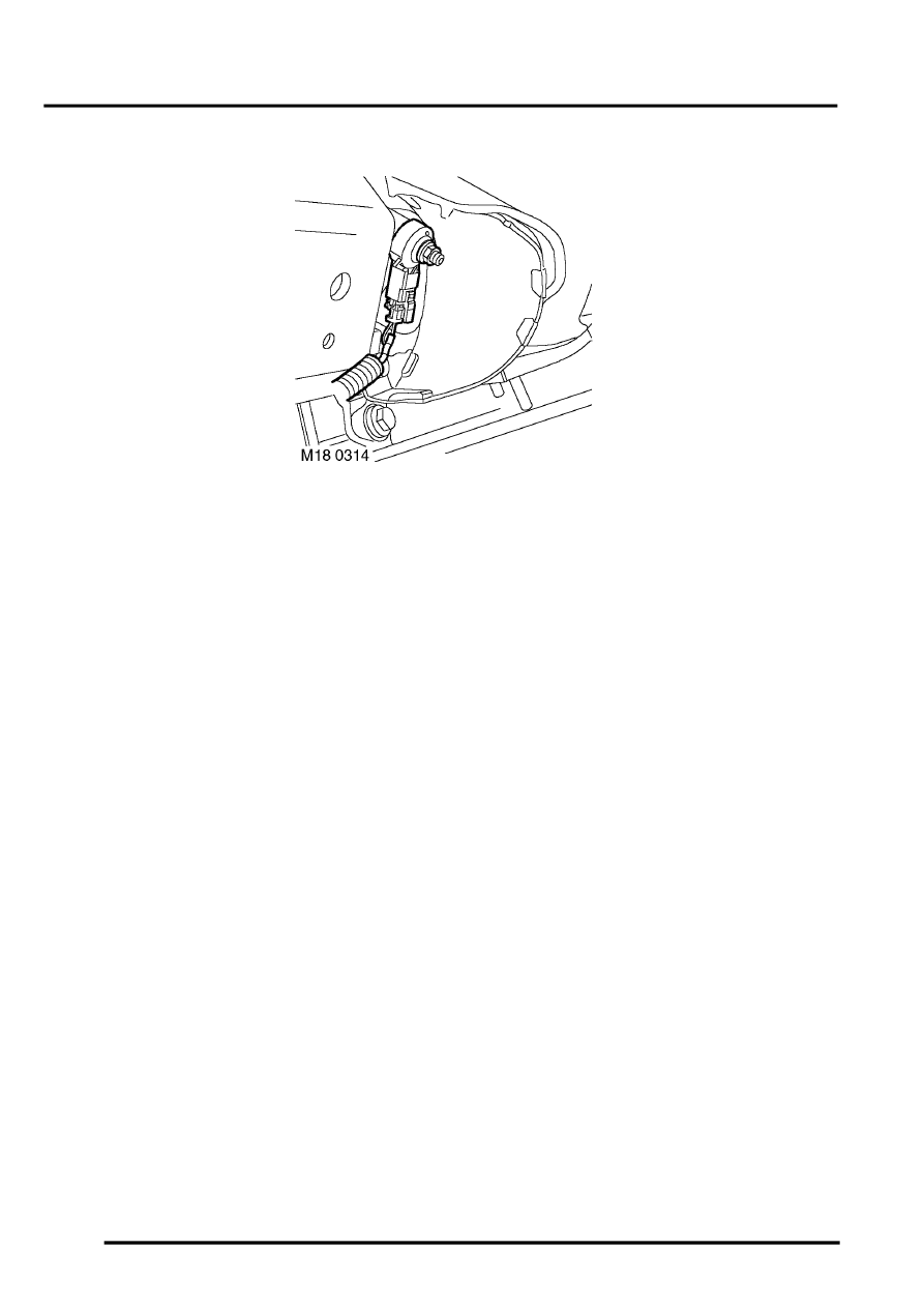
Knock Sensor (KS)
The ECM uses two knock sensors located between the centre two cylinders of each bank to detect pre-ignition. The
knock sensors consist of piezo ceramic crystals that oscillate to create a voltage signal. During pre-ignition the
frequency of crystal oscillation increases, which alters the signal output to the ECM. The ECM compares the signal
to known signal profiles in its memory. If pre-ignition is detected the ECM retards ignition timing for a number of cycles.
If no more pre-ignition is detected, the timing is gradually advanced to the original setting.
The ignition is calibrated to run on 95 RON premium fuel, but the system will run satisfactorily on 91 RON regular fuel.
If the vehicle is refuelled with a lower grade fuel, some audible detonation will initially be heard. This is non-damaging
and ceases when the system adaption is completed.
Input/Output
Because of the nature of its operation, the knock sensors do not require any electrical input source. The KS output
for LH bank (cylinders 1, 3, 5, 7) is measured via pin 49 of connector C0636 of the ECM. The KS output for RH bank
(cylinders 2, 4, 6, 8) is measured via pin 36 of connector C0636 of the ECM. Both knock sensors have a screened
earth to protect the integrity of the sensor signals. The KS earth for LH bank (cylinders 1, 3, 5, 7) is via pin 48 of
connector C0636 of the ECM. The KS earth for RH bank (cylinders 2, 4, 6, 8) is via pin 35 of connector C0636 of the
ECM.
The connector and sensor terminals are gold plated for corrosion and temperature resistance, care must be exercised
while probing the connector and sensor terminals.
The KS can fail the following ways or supply incorrect signal:
l
Sensor open circuit.
l
Short circuit to vehicle battery supply.
l
Short circuit to vehicle earth.
l
Faulty component.
l
Incorrectly tightened sensor.
In the event of a KS signal failure any of the following symptoms may be observed:
l
KS disabled, the ECM refers to a 'safe ignition map'.
l
Rough running.
l
Engine performance concern.
Parts & tools for this job Staging For Land Rover Discovery
- PARTEngine gasket setSearch: Land Rover Discovery engine gasket set
- TOOLTorque wrenchSearch: 3/8 inch torque wrench
- TOOLFeeler gauge setSearch: feeler gauge set
Links open Amazon search results in a new tab. As an Amazon Associate I earn from qualifying purchases.