
Description - engine management (ENGINE MANAGEMENT SYSTEM - V8) (page 35 of 43)
- Make
- Land Rover
- Model
- Discovery II (NAS)
- Section
- DESCRIPTION AND OPERATION
ENGINE MANAGEMENT SYSTEM - V8
18-2-40 DESCRIPTION AND OPERATION
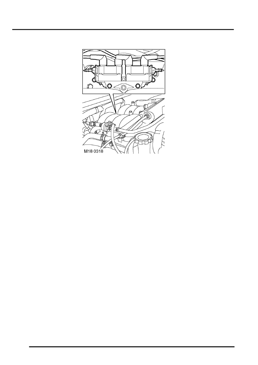
Ignition coils
Two double ended ignition coils are located at the rear of the engine, below the inlet plenum camber mounted on a
bracket. The ignition system operates on the wasted spark principle. When the ECM triggers an ignition coil to spark,
current from the coil travels to one spark plug jumping the gap at the spark plug electrodes igniting the mixture in the
cylinder. Current continues to travel along the earth path (via the cylinder head) to the spark plug negative electrode
at the cylinder that is on the exhaust stroke. The current jumps across the spark plug electrodes and back to the coil
completing the circuit. Since it has sparked simultaneously in a cylinder that is on the exhaust stroke it has not done
any work, therefore it is wasted.
The coils are paired in the following cylinder order:
l
1 and 6.
l
8 and 5.
l
4 and 7.
l
3 and 2.
The ECM calculates the dwell timing from battery voltage, and engine speed to ensure constant secondary energy.
This ensures sufficient spark energy is always available without excessive primary current flow and thus avoiding
overheating or damage to the coils. Individual cylinder spark timing is calculated from the following signals:
l
Engine speed.
l
Engine load.
l
Engine temperature.
l
Knock control.
l
Automatic gearbox shift control.
l
Idle speed control.
During engine warm up ignition timing should be an expected value of 12
°
BTDC.
TestBook can not directly carry out diagnostics on the high-tension side of the ignition system. Ignition related faults
are monitored indirectly by the misfire detection system.
Parts & tools for this job Staging For Land Rover Discovery
- PARTEngine gasket setSearch: Land Rover Discovery engine gasket set
- TOOLTorque wrenchSearch: 3/8 inch torque wrench
- TOOLFeeler gauge setSearch: feeler gauge set
Links open Amazon search results in a new tab. As an Amazon Associate I earn from qualifying purchases.