
Description - engine management (ENGINE MANAGEMENT SYSTEM - V8) (page 33 of 43)
- Make
- Land Rover
- Model
- Discovery II (NAS)
- Section
- DESCRIPTION AND OPERATION
ENGINE MANAGEMENT SYSTEM - V8
18-2-38 DESCRIPTION AND OPERATION
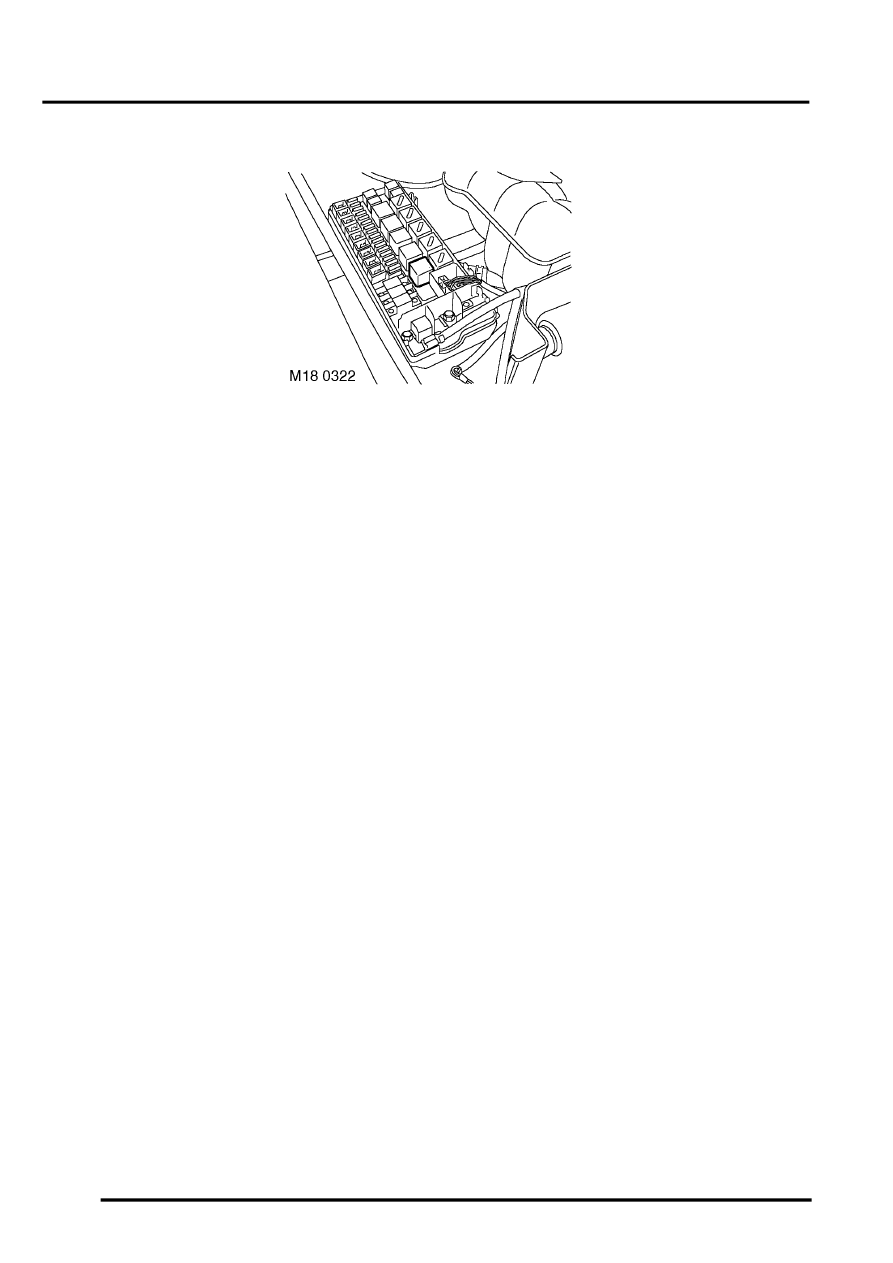
Fuel pump relay
The fuel pump relay is located in the engine compartment fuse box. It is a 4 pin normally open relay. Input from the
ECM allows the fuel pump relay to control the electrical input to the fuel pump, regulating the fuel supply to the fuel
injectors. When the ignition is switched on and the engine is cranked, the fuel pump relay is activated by the ECM,
allowing the fuel system to be pressurised to 3.5 bar (52 lbf.in
2
). The ECM then deactivates the relay until the engine
has started.
If the fuel pump runs, but the fuel pressure is out of limits, adaptive fuel faults will be stored.
Input/Output
The input value for the relay windings is battery voltage, the input value for the switching contacts comes from fuse
10 in the engine compartment fuse box. The output control of the switching contacts is direct to the fuel pump motor,
and the relay windings are controlled by pin number 18 of connector C0635 of the ECM.
At ignition 'on' (position II) the fuel pump relay contacts remain open until the ECM supplies an earth path for the relay
windings via pin number 18 of connector C0635 of the ECM. At this point, the relay windings are energised, drawing
the relay contacts closed. This allows voltage from fuse 10 in the passenger compartment fuse box to pass directly
to the fuel pump.
The fuel pump relay can fail the following ways or supply incorrect signal:
l
Relay drive open circuit.
l
Short circuit to vehicle earth.
l
Short circuit to vehicle supply.
l
Component failure.
In the event of a fuel pump relay failure any of the following symptoms may be observed:
l
Engine stalls or will not start.
l
No fuel pressure at the fuel injectors.
The ECM performs three types of diagnostic test to confirm the fuel pump relay integrity:
l
Output short circuit to earth
l
Output short circuit to battery voltage
l
Output open circuit
Parts & tools for this job Staging For Land Rover Discovery
- PARTEngine gasket setSearch: Land Rover Discovery engine gasket set
- TOOLTorque wrenchSearch: 3/8 inch torque wrench
- TOOLFeeler gauge setSearch: feeler gauge set
Links open Amazon search results in a new tab. As an Amazon Associate I earn from qualifying purchases.