
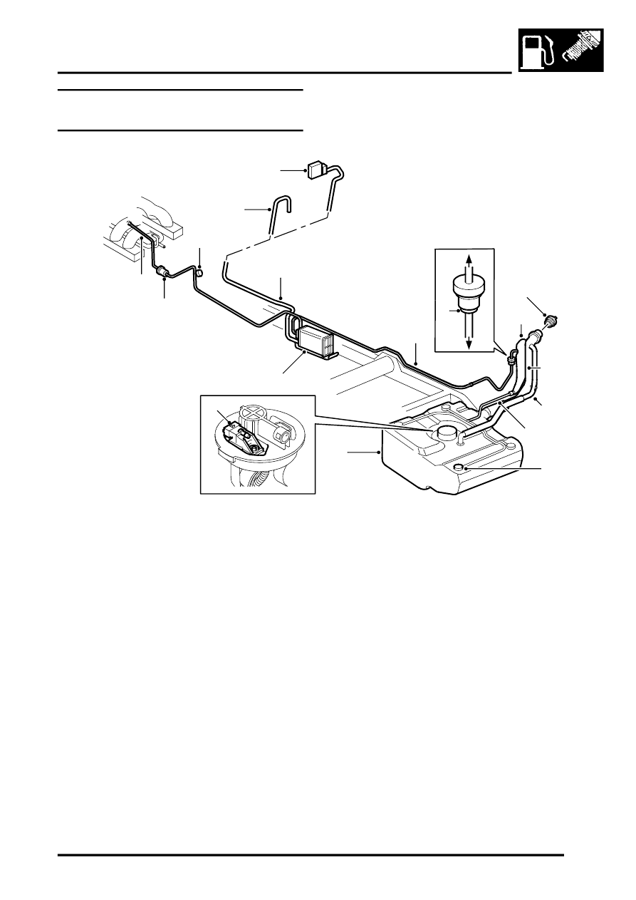
Evaporative emission system component layout (EMISSION CONTROL - V8)
- Make
- Land Rover
- Model
- Discovery II
- Section
- DESCRIPTION AND OPERATION › Evaporative emission system component layout
EMISSION CONTROL - V8
DESCRIPTION AND OPERATION
17-2-3
Evaporative emission system
component layout
1 Purge valve
2 Service port
3 Snorkel tube (UK / ROW only)
4 CVS unit (NAS vehicles with vacuum type leak
detection only)
5 EVAP canister breather tube
6 Vent pipe – fuel tank to EVAP canister
7 Relief valve regulated flow
8 Relief valve (UK / ROW only)
9 Relief valve free flow
10 Fuel filler cap
11 Liquid vapour separator #
(UK / ROW type shown)
12 Fuel filler hose (UK / ROW type shown)
13 Tank breather hose (UK / ROW only)
14 Vent hose
15 Roll over valves (ROV's) –
(4 off, UK / ROW spec. shown)
16 Fuel tank and breather assembly
17 EVAP canister
18 Purge line connection to engine manifold
19 Tank EVAP system pressure sensor (NAS
vehicles with vacuum type leak detection only)
M17 0209
4
3
1
6
5
16
10
8
13
17
9
7
11
12
15
14
18
2
19
Parts & tools for this job Staging For Land Rover Discovery
- PARTExhaust gasketSearch: Land Rover Discovery exhaust gasket
- TOOLPenetrating oilSearch: penetrating oil
- TOOLOBD2 scannerSearch: OBD2 scanner
Links open Amazon search results in a new tab. As an Amazon Associate I earn from qualifying purchases.