
DRIVING AIDS: DESCRIPTION AND OPERATION (page 2 of 2)
- Make
- Land Rover
- Model
- Discovery II
DRIVING AIDS
86-8-12 DESCRIPTION AND OPERATION
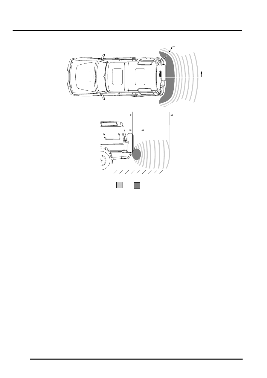
Park Distance Control Detection Areas
a Intermittent Warning Tone
b Continuous Warning Tone
Detection Calculation
When operating in the combined transmitter and receiver mode, the sensor outputs a number ultrasonic pulses and
receives the reflected echo signal. The ECU amplifies the received echo signals and compares them with a
preprogrammed threshold to calculate the distance to the object. This is achieved by determining the elapsed time
between the transmission and reception of the ultrasonic signal.
When operating in receiver mode, the sensor receives echo signals transmitted by an adjacent sensor. This mode is
used to improve the accuracy of the system.
The detection cycle consists of the ECU operating one sensor in the combined transmitter and receiver mode and
transmitting a number of ultrasonic pulses. The ECU then switches the transmitting sensor and the adjacent sensor(s)
to receiver mode. After a short time delay, this sequence is repeated using a different sensor to transmit the ultrasonic
pulse and continues until all four sensors have output an ultrasonic signal. This sequence is completed in 100ms. The
ECU uses several measurements of the same sensors to remove errors from the calculation.
If the object is directly behind a sensor, the distance is calculated using the time between the transmission and
reception of the signal. If the object is positioned between two sensors, the ECU uses both signals to determine the
correct distance using triangulation.
To perform the triangulation calculation, the ECU must know the distance between the individual sensors in the
bumper. This information is stored in the ECU memory. From the received distance from each sensor and using the
known distance between adjacent sensors, the ECU can calculate the minimum distance from the vehicle to the
object.
When approaching several objects, the ECU recognises the distance from the vehicle to the nearest object.
A
Y-Y
1800mm (70in)
450mm (17in)
600mm (23.5in)
Y
Y
B
M86 5917
Parts & tools for this job Staging For Land Rover Discovery
- TOOLTorque wrenchSearch: 3/8 inch torque wrench
- TOOLSocket setSearch: socket set metric
- BOOKHaynes manualSearch: Haynes manual Land Rover Discovery
Links open Amazon search results in a new tab. As an Amazon Associate I earn from qualifying purchases.