
DRIVING AIDS (Description): DESCRIPTION AND OPERATION (page 6 of 7)
- Make
- Land Rover
- Model
- Discovery II
- Section
- DESCRIPTION AND OPERATION
DRIVING AIDS
DESCRIPTION AND OPERATION
86-8-9
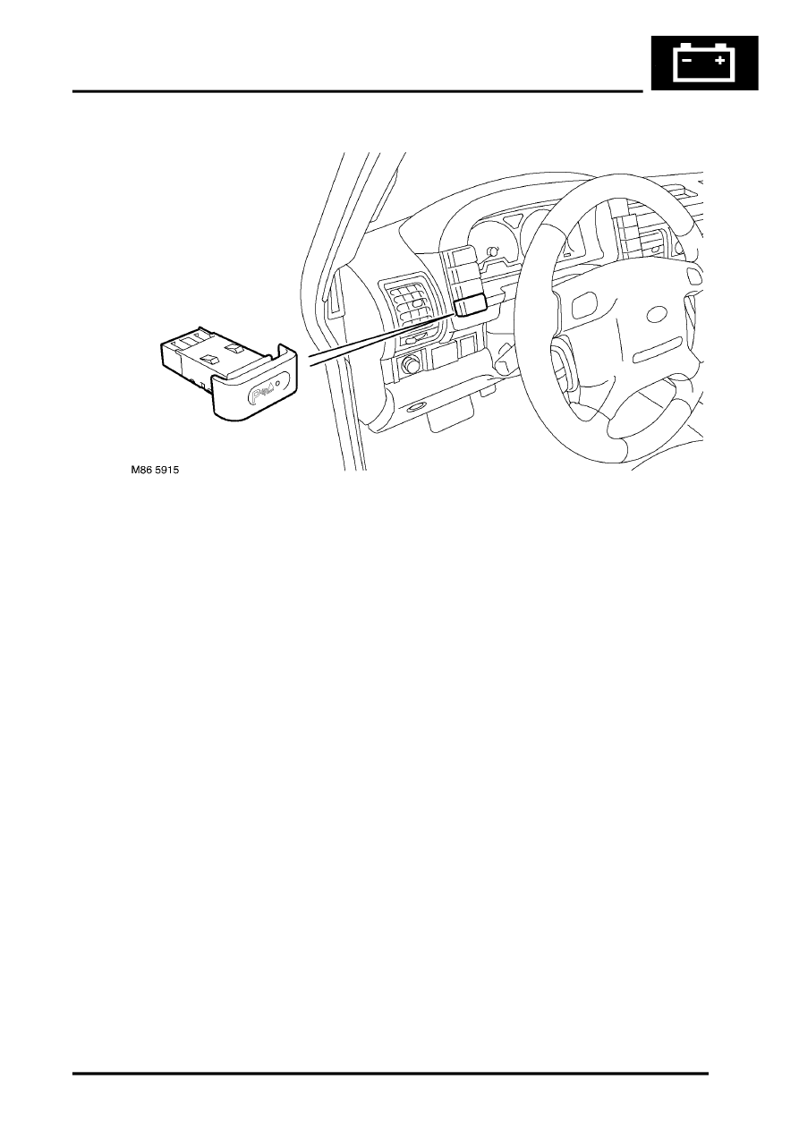
PDC Switch
The PDC switch is located in the instrument pack cowl, below the fuel flap release switch. The switch has a
momentary, non-latching action, which switches a positive output from the PDC ECU to ground when pressed. This
signal is used by the ECU to switch the PDC between the activated and de-activated conditions. The switch is
connected to the PDC ECU via a harness connector which is integrated into the vehicle body harness.
The switch contains an LED. The LED illuminates for approximately 3 seconds when the ignition is switched to
position II for a bulb check. The bulb check is controlled by logic within the PDC ECU. When the system is active (i.e.
obstacle detected), the LED illuminates to show the active condition.
When the PDC is switched from the off condition to the active condition, the LED is illuminated briefly, along with a
chime from the sounder, to signal that the system has been activated.
If a fault exists in the PDC system, the ECU flashes the LED continuously, when the switch is pressed to activate the
system.
Parts & tools for this job Staging For Land Rover Discovery
- TOOLTorque wrenchSearch: 3/8 inch torque wrench
- TOOLSocket setSearch: socket set metric
- BOOKHaynes manualSearch: Haynes manual Land Rover Discovery
Links open Amazon search results in a new tab. As an Amazon Associate I earn from qualifying purchases.