
BODY CONTROL UNIT: DESCRIPTION AND OPERATION (page 9 of 16)
- Make
- Land Rover
- Model
- Discovery II
BODY CONTROL UNIT
DESCRIPTION AND OPERATION 86-3-27
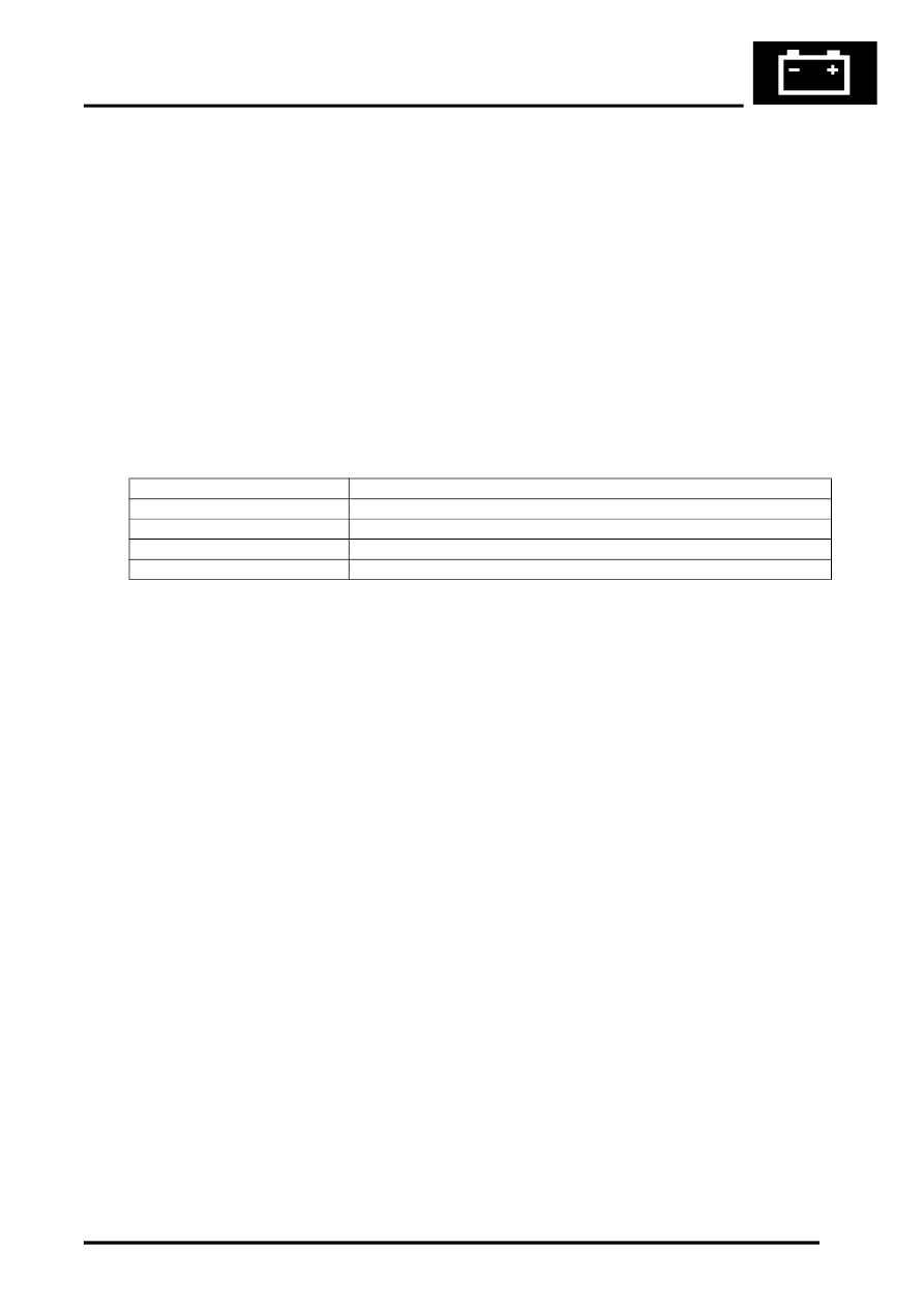
If a direction indicator bulb failure or a trailer presence is detected, the following outputs can be generated depending
on the BCU logic states:
l
Trailer detected.
l
Bulb failure detected.
l
Direction indicator short circuit.
l
Direction indicator relay stuck.
The BCU can be configured whether or not to provide bulb failure warnings.
When the direction indicators are operating, instrument pack direction indicators flash in sequence with the exterior
direction indicators. If a failure of an indicator bulb occurs, the corresponding instrument pack indication lamp will flash
quickly to warn of the problem.
The IDM monitors the current drawn through the circuit to detect for the occurrence of a lamp failure. If an indicator
lamp fails, the IDM detects the drop in current drawn through the resistor and operates the indicator relay at a faster
speed. The fast flash is demonstrated on the instrument pack direction indicator warning lamps to bring attention to
the driver that a direction indicator bulb failure has occurred. The current sense for the related indicator lamps (RH or
LH) are checked when a direction indicator request has been made that lasts for at least 160 ms. The current level
sensed is relative to the number of working bulbs and determines the request generated by the BCU.
The output is signalled to the instrument pack using the serial communications link. If the hazard warning lamps are
operating, both sets of direction indicators are checked using the current sensing functions to check the number of
bulbs on each side of the vehicle.
If the BCU detects that a direction indicator request has not been made, but one or other of the current sense inputs
indicate that current is flowing, a 'Relay stuck' output is generated.
Hazard lamps
The BCU controls the operation of the hazard warning lamps via the IDM and dedicated relays. The hazard warning
lamps are activated under the following conditions:
l
The vehicle is locked and the security system is set (the hazard warning lamps flash three times if the
superlocking feature is used, once if not).
l
The vehicle is unlocked (the hazard warning lamps flash once for a duration of two seconds).
l
The anti-theft alarm system is triggered (the hazard warning lamps flash in phase with and for the duration of the
audible warning).
l
The hazard warning switch is pressed (the hazard warning lamps flash until the hazard warning switch is pressed
for a second time).
l
The inertia switch is triggered (the hazard warning lamps flash until the inertia switch has been reset).
The hazard warning lamp operation may differ dependent on market and customer configuration options.
The hazard warning lamps are operated from a latching pushbutton switch located on the fascia. When the switch is
pressed, both left and right indicator lamps in the instrument pack flash to show that the hazard warning lamps are
operating and all hazard warning lamps flash simultaneously. If a trailer is fitted, the ICM detects this and a trailer
symbol in the instrument pack also flashes to show correct operation of the trailer direction indicators and hazard
warning lamps.
The BCU supplies a reference voltage to the hazard warning switch. When the hazard warning switch is operated an
earth path is completed which signals the BCU that a request for hazard lamp operation has been made. The BCU
then sends a signal to the IDM via the serial data bus to communicate the request. The IDM supplies an earth path
for both direction indicator relay coils simultaneously so that the hazard warning lamps are turned on concurrently.
The IDM controls the timing of the flash operations by continually removing and restoring the earth path to both
direction indicator relay coils simultaneously.
Number of working bulbs
Request generated
3
Trailer detected
2
None (bulbs okay)
1
Bulb failure detected
0
Direction indicator short circuit detected
Parts & tools for this job Staging For Land Rover Discovery
- TOOLTrim removal tool kitSearch: trim removal tool kit
- PARTTouch-up paintSearch: Land Rover touch up paint
- PARTPanel clip assortmentSearch: Land Rover panel clips assortment
Links open Amazon search results in a new tab. As an Amazon Associate I earn from qualifying purchases.