
AUTOMATIC GEARBOX - ZF4HP22 - 24 (Description): DESCRIPTION AND OPERATION (page 9 of 13)
- Make
- Land Rover
- Model
- Discovery II
- Section
- DESCRIPTION AND OPERATION
AUTOMATIC GEARBOX - ZF4HP22 - 24
44-12
DESCRIPTION AND OPERATION
Reverse gear
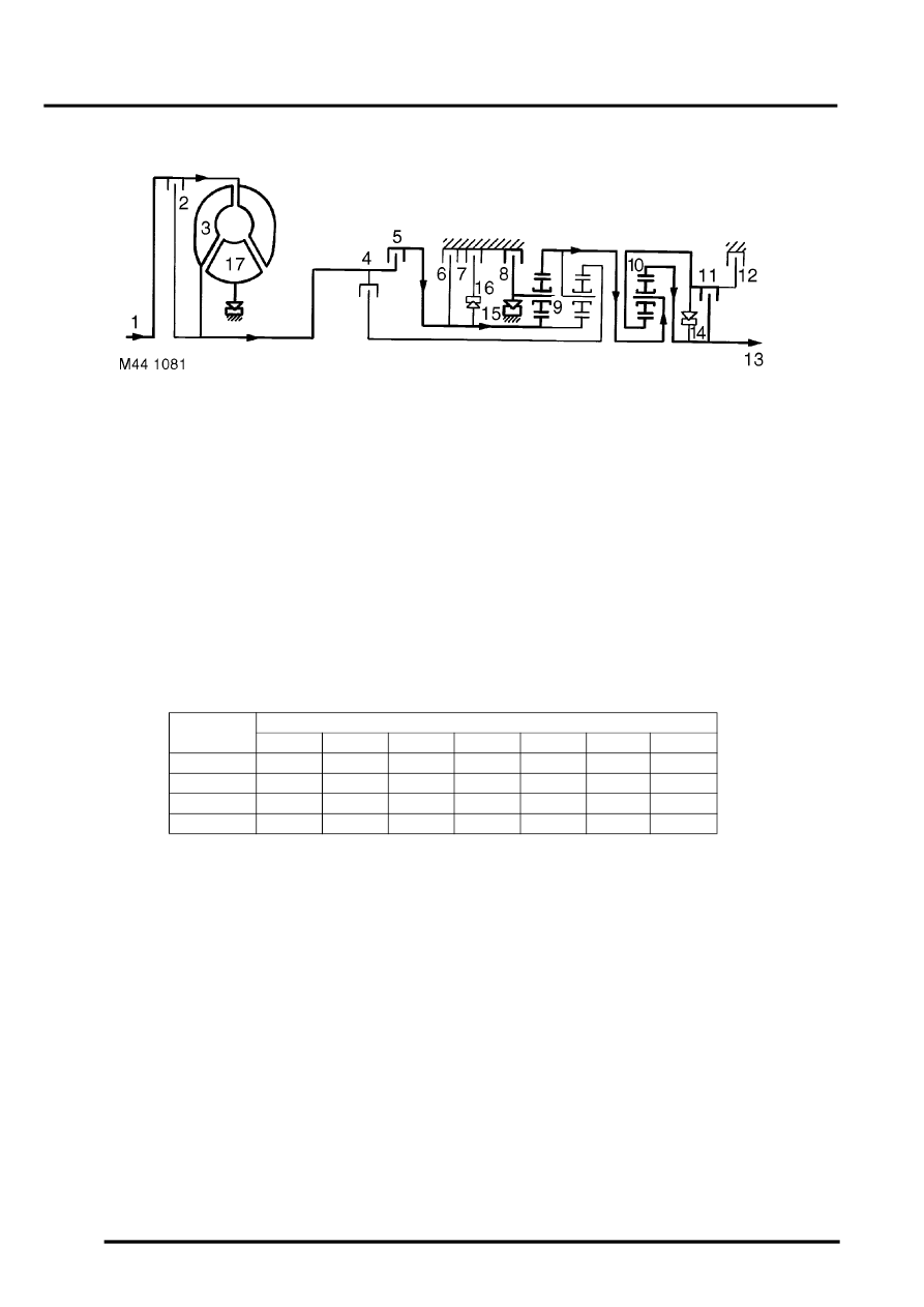
Clutches (5), (8) and (11) are engaged. The front planet gear carrier of gear set (9) is locked. Gear set (10) also rotates
as a solid block.
Gear position switch
The gear position switch outputs signals that are related to the position of the selector lever assembly. The switch is
installed on the selector shaft on the left side of the gearbox. Slotted mounting holes allow the switch to be turned
relative to the shaft for adjustment. A fly lead connects the switch to the vehicle wiring.
Movement of the selector lever assembly turns the selector shaft, which operates six pairs of contacts in the switch.
The pairs of contacts are identified as the W, X, Y, Z, Park/Neutral and Reverse contacts. When closed:
l
The W, X, Y and Z contacts output a 12V ignition supply from the BCU.
l
The Park/Neutral contacts output an earth.
l
The Reverse contacts output a 12V ignition supply from the passenger compartment fuse box.
The outputs of the W, X, Y and Z contacts are monitored by the EAT ECU and the BCU to determine the position of
the selector lever assembly.
Gear position switch W, X, Y, Z outputs
The Park/Neutral contacts output to the BCU and, on diesel models, the ECM. The Reverse contacts output to the
BCU, the reversing lamps, the SLABS ECU and, where fitted, the ACE ECU and the electrochromic interior mirror.
Switch
contacts
Output
P
R
N
D
3
2
1
W
12V
-
12V
12V
-
-
-
X
-
12V
12V
-
12V
-
-
Y
-
-
12V
12V
12V
-
12V
Z
-
-
-
12V
12V
12V
-
Parts & tools for this job Staging For Land Rover Discovery
- PARTTransmission filter kitSearch: Land Rover Discovery transmission filter kit
- FLUIDAutomatic transmission fluidSearch: Land Rover automatic transmission fluid
- TOOLFluid transfer pumpSearch: fluid transfer pump
Links open Amazon search results in a new tab. As an Amazon Associate I earn from qualifying purchases.