
Power unit with manual gearbox - r + r
- Make
- Alfa Romeo
- Model
- GT Factory Service Manual
- Year
- 2003–2010
- Section
- Engine and power unit › Power unit with manual gearbox - r + r
POWER UNIT WITH MANUAL GEARBOX - R + R
Removing
Position the vehicle on a lift.
PROCEED WITH DRAINING THE HIGH PRESSURE FUEL SYSTEM FOLLOWING THE INSTRUCTIONS GIVEN BELOW.
Start the engine.
Keep the engine idling for 2 minutes.
Detach the fuel pump relay.
Wait until the engine cuts out.
Try and start the engine: if the engine starts within 10 seconds wait for it to cut out, then try and start the engine again; if the engine does not start within 10 seconds, continue for another 5 seconds.
Wait for the engine to cool down.
Drain the air conditioning refrigerant circuit
Op. 0010T84 COOLANT FOR AIR CONDITIONING SYSTEM DEHYDRATE AND RECHARGE.
Proceed with the removal
Op. 4450B12 FRONT OR REAR WHEELS (TWO) - R+R.
Proceed with the removal
Op. 7055B64 LH OR RH REFLECTOR(ONE) ON REAR BUMPERS - R R.
Proceed with the removal
Op. 7055B54 UNDER-ENGINE GUARD - R R.
1. Disconnect the rapid connector for the lower coolant outlet hose from the radiator and drain the engine cooling system.
Manually press the clips and release the hose rapid connector.
Reconnect the rapid connector for the radiator lower coolant outlet hose.
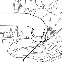
Proceed with the removal
Op. 1016A40 IGNITION COIL COVER ON CYLINDER HEAD- R+R.
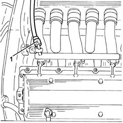
1. Disconnect the rapid connector for the fuel supply pipe and release it from the fastening on the modular intake manifold.
2. Disconnect the rapid connector for the fuel vapour recovery pipe.
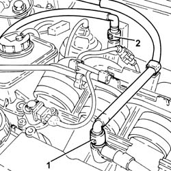
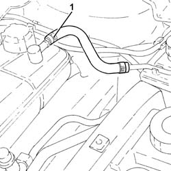
1. Loosen the coolar and disconnect the coolant return pipe from the engine coolant reservoir.
1. Loosen the band and disconnect the system supply pipe from the water pump rigid inlet pipe.
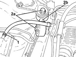
2. Undo the bolt (2a) and disconnect the inlet/outlet pipes flange (2b) from the air conditioning compressor.
Seal the connectors that have been disconnected using suitable plugs to prevent dampness and impurities from entering the system.
3. Disconnect the electrical connection for the right upper Lambda sensor.
| Description | Connector | |
|---|---|---|
| 3 | Lambda sensor on pre-catalyzer - 2 | See K16 LAMBDA SENSOR ON PRE-CATALYZER -2 ( CONNECTORS ) |
4. Disconnect the electrical connection for the right rear Lambda sensor to the catalytic converter.
| Description | Connector | |
|---|---|---|
| 4 | Lambda sensor on catalyzer - 2 | See K18 LAMBDA SENSOR ON CATALYZER 2 ( CONNECTORS ) |
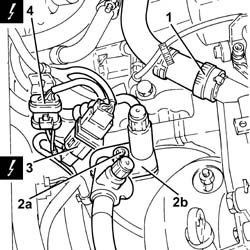
Proceed with the removal
Op. 1008C10 POWER UNIT UPPER REACTION LINK R R.
Proceed with the removal
Op. 1048A59 PIPE from flow meter to throttle casing hose - R.R..
Proceed with the removal
Proceed with the removal
Op. 5530B52 BATTERY DRIP TRAY/SUPPORT - R.R..
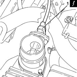
1. Disconnect the electrical connection from the air flow meter.
| Description | Connector | |
|---|---|---|
| 1 | Air flow meter | See K41 AIR FLOW METER ( FRONT ) |
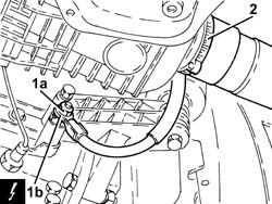
1. Undo the nut (1a) and disconnect the earth lead (1b).
| Description | Connector | |
|---|---|---|
| 1b | Battery earth | See C1 BATTERY EARTH |
2. Loosen the band and disconnect the cold air intake from the air filter.
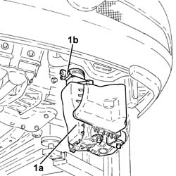
1. Remove the air filter (1a) complete with air flow meter (1b).
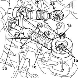
1. Remove the clip (1a), press the springs (1b) and disconnect the gear engagement cable (1c).
2. Press the springs (2a) and disconnect the gear selector cable (2b).
3. Undo the bolts (3a) and move the bracket (3b) complete with gear selector and engagement cables to the side.
1. Disconnect the electrical connection from the reversing light switch.
| Description | Connector | |
|---|---|---|
| 1 | Reversing lights switch | See I20 REVERSING LIGHTS SWITCH |
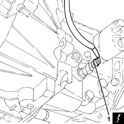
1. Move the protective cover away.
2. Remove the cap from the bleed valve.
3. Connect the recovery device (pipe and reservoir) to the bleed valve on the clutch hydraulic actuator.
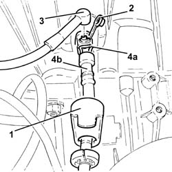
4. Raise the retaining clip (4a) until the first click is heard and remove pipe (4b) by a sufficient amount to uncover the bleed hole.
Leave the hydraulic clutch system to drain completely.
Lift up the spring completely and disconnect the pipe from the hydraulic clutch control actuator.
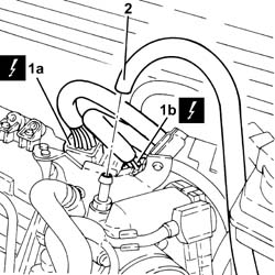
1. Disconnect the engine wiring electrical connections (1a) and (1b).
| Description | Connector | |
|---|---|---|
| 1a | Front/engine coupling | See D4A FRONT/ENGINE CONNECTION ( CONNECTORS ) |
| Description | Connector | |
|---|---|---|
| 1b | Front/engine coupling | See D4B FRONT/ENGINE CONNECTION ( CONNECTORS ) |
2. Loosen the band and disconnect the vacuum intake pipe from the modular intake manifold.
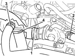
1. Loosen the collar and disconnect the upper coolant input sleeve to the radiator, thermostat side.
2. Loosen the collar and disconnec the coolant delivery pipe to the climate control system heater, thermostat side.
3. Loosen the collar and disconnect the coolant outlet pipe from the climate control system heater, on the side of the rigid pipe carrying coolant into the coolant pump.
4. Loosen the band and disconnect the lower coolant inlet hose from the radiator, water pump rigid coolant inlet pipe side.
Drain the power assisted steering fluid reservoir using a suitable syringe.
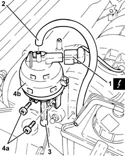
1. Disconnect the electrical connection from the switching control actuator enablement solenoid valve.
| Description | Connector | |
|---|---|---|
| 1 | Variable geometry solenoid valve | See L15 VARIABLE GEOMETRY CONTROL SOLENOID ( CONNECTORS ) |
2. Disconnect the vacuum intake pipe from the air flow switching device actuator and release it from the fastening on the latter.
3. Disconnect the air flow switching device actuator linkage.
4. Undo the bolts (4a) and remove the air flow switching device control actuator (4b).
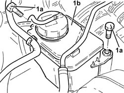
Release the power assisted steering fluid reservoir supply and return pipes from the connecting band.
1. Undo the bolts (1a) and move the power assisted steering fluid reservoir (1b) sideways.
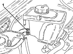
1. Loosen the band and disconnect the power assisted steering fluid reservoir return pipe, reservoir side.
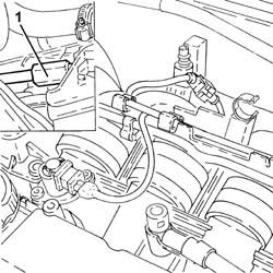
1. Undo the connector and disconnect the supply pipe from the pump to the power assisted steering box, power assisted steering pump side.
Proceed with the removal
Op. 1088E10 RADIATOR COOLING FAN - R + R.
1. Disconnect the electrical connection for the left upper Lambda sensor.
| Description | Connector | |
|---|---|---|
| 1 | Lambda sensor on pre-catalyzer | See K15 LAMBDA SENSOR ON PRE-CATALYZER |
2. Disconnect the electrical connection for the left rear Lambda sensor to the catalytic converter.
| Description | Connector | |
|---|---|---|
| 2 | Lambda sensor on catalyzer | See K17 LAMBDA SENSOR ON CATALYZER ( CONNECTORS ) |
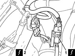
Proceed with the removal
Op. 1076B18 RIGID SECTION OF EXHAUST PIPE BETWEEN CATALYTIC CONVERTER AND SILENCER - R + R.
Disconnect the electrical connections from the starter motor.
| Description | Connector | |
|---|---|---|
| Starter motor | See A20 STARTER'' MOTOR |
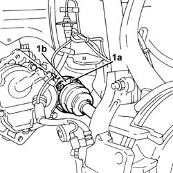
1. Undo the bolts (1a) and disconnect the flanges for the driveshaft constant velocity joints (1b).
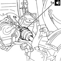
The bolts fixing the front driveshafts, intermediate driveshaft/differential internal driveshaft, have been treated with eslok; they should therefore be replaced each time they are removed.
Remove the safety plates.
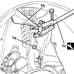
1. Undo the nut (1a) and disconnect the steering knuckles (1b) from the upper track control arms using the tool (1c).
| Description | Code | |
|---|---|---|
| 1c | Extractor | 1.821.169.000 |
Release the front brake caliper flexible pipes and the A.B.S. sensor cables from the mounting brackets.
Move the left driveshaft as far away as possible from the differential and the right driveshaft away from the intermediate driveshaft.
Postion a suitable footboard beneath the power unit.
1. Position suitable brackets on the power unit as illustrated in the diagram.
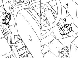
1. Support the power unit using a hydraulic hoist (1a) and the tool (1b) connected to the brackets fitted previously.
| Description | Code | |
|---|---|---|
| 1b | Balance | 1.871.001.700 |
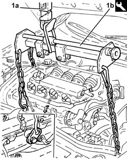
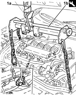
1. Unscrew the bolt securing the power unit rigid rear support to the flexible mounting.
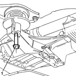
1. Undo the bolts (1a), (1b) and remove the power unit gearbox side rigid support (1c).
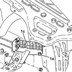
1. Unscrew the bolt securing the timing side rigid engine support to the flexible mounting.
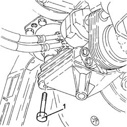
Slowly lower the power unit with the hydraulic hoist until it rests on the board positioned previously.
Hoist and support the power unit using a hydraulic hoist, then release it from the tools used for the removal.
Refitting
Place the power unit in the engine compartment using a hydraulic hoist fitted with a suitable tool.
| Description | Code | |
|---|---|---|
| 2b | Balance | 1.871.001.700 |
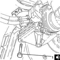
1. Tighten the bolt securing the timing side rigid engine support to the flexible mounting to the recommended torque.
| Fastening | Component | Ø | Value (daNm) | |
|---|---|---|---|---|
| 1 | Bolt | RIGID ENGINE MOUNT, TIMING SIDE | M12 | (Flexible mounting side) 7.9 - 9.7 |
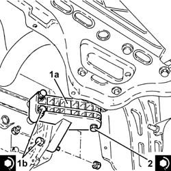
1. Place the power unit gearbox side rigid support (1a) in its housing and secure it tightening the bolts (1b) to the recommended torque.
| Fastening | Component | Ø | Value (daNm) | |
|---|---|---|---|---|
| 1b | Bolt | POWER UNIT GEAR BOX END RIGID MOUNT | M10 | (Gearbox side) 4.5 - 5.5 |
2. Tighten the bolt securing the power unit gearbox side rigid support to the flexible mounting to the recommended torque.
| Fastening | Component | Ø | Value (daNm) | |
|---|---|---|---|---|
| 2 |
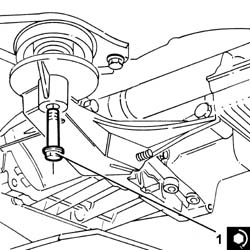
1. Tighten the bolt securing the power unit rigid rear support to the flexible mounting.
| Fastening | Component | Ø | Value (daNm) | |
|---|---|---|---|---|
| 1 |
Remove the tools used for refitting the power unit and put them away.
Fasten the front brake caliper flexible pipes and the A.B.S. sensor cables to the mounting brackets.
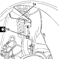
1. Connect the steering knuckles to the upper track control arms (1a) and secure them tightening the nut (1b) to the recommended torque.
| Fastening | Component | Ø | Value (daNm) | |
|---|---|---|---|---|
| 1b | Nut | FRONT HUB STRUT | M10 | (Upper track control arm side) 4.3 - 4.7 |
1. Position the safety plates and tighten the new bolts (1a) for the flanges for the driveshaft constant velocity joints (1b) to the recommended torque.
| Fastening | Component | Ø | Value (daNm) | |
|---|---|---|---|---|
| 1a | Bolt | DRIVESHAFT COMPLETE WITH JOINTS | M8 | (Intermediate driveshaft/differential internal shaft side) 3.6 - 4.4 |
Connect the electrical connections to the starter motor.
Proceed with the refitting
Op. 1076B18 RIGID SECTION OF EXHAUST PIPE BETWEEN CATALYTIC CONVERTER AND SILENCER - R + R.
Connect the electrical connection for the left rear Lambda sensor to the catalytic converter.
Connect the electrical connection for the left upper Lambda sensor.
Proceed with the refitting
Op. 1088E10 RADIATOR COOLING FAN - R + R.
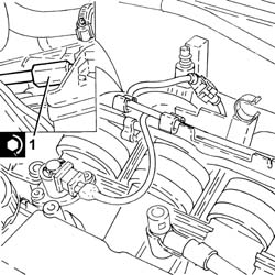
1. Connect the supply pipe from the pump to the power assisted steering box, power assisted steering pump side and tighten the connector to the recommended torque.
| Fastening | Component | Ø | Value (daNm) | |
|---|---|---|---|---|
| 1 | Connector | PIPE BTWN PUMP + POWER STEERING BOX | M16 | (Power assisted steering pump side) 4.5 - 5.5 |
Connect the power assisted steering fluid return pipe to the reservoir and tighten the band.
Place the power assisted steering fluid reservoir in its housing and secure it using the bolts.
Fasten the power assisted steering fluid reservoir supply and return pipes to the connecting band.
Place the air flow switching device control actuator back in its housing and secure it using the bolts.
Connect the air flow switching device actuator linkage.
Connect the vacuum intake pipe from the air flow switching device actuator and secure it to the latter.
Connect the electrical connection to the switching control actuator enablement solenoid valve.
Connect the lower coolant inlet hose from the radiator, water pump rigid coolant inlet pipe side and tighten the band.
Connect the coolant outlet pipe from the climate control system heater, on the side of the rigid pipe carrying coolant into the coolant pump and tighten the collar.
Connect the coolant delivery pipe to the climate control system heater, thermostat side, and tighten the band.
Connect the upper coolant input sleeve to the radiator, thermostat side, and tighten the band.
Connect the vacuum intake pipe to the modular intake manifold and tighten the band.
Connect the electrical connections for the engine wiring.
Fit the pipe fully home in its seat on the hydraulic clutch actuator and secure with the retaining clip.
Place the cap in its housing on the bleed valve.
Place the protective cover in its housing.
Connect the electrical connection to the reversing light switch.
Place the bracket complete with gear selector and engagement cables in position and secure it using the bolts.
Connect the gear selector cable.
Connect the gear engagement cable and fasten it using the clip.
Refit the air filter with air flow meter in its seat.
Connect the cold air intake to the air filter and fasten it using the band.
Connect the earth lead and tighten the nut.
Connect the electrical connection to the air flow meter.
Proceed with the refitting
Op. 5530B52 BATTERY DRIP TRAY/SUPPORT - R.R..
Proceed with the refitting
Proceed with the refitting
Op. 1048A59 PIPE from flow meter to throttle casing hose - R.R..
Proceed with the refitting
Op. 1008C10 POWER UNIT UPPER REACTION LINK R R.
Connect the electrical connection for the right rear Lambda sensor to the catalytic converter.
Connect the electrical connection for the right upper Lambda sensor.
Connect the flange for the air conditioning compressor inlet/outlet pipes and secure it by tightening the bolt to the recommended torque.
Replace the O rings for the connectors. Only use green coloured seals that are resistant to R134a refrigerant fluid. Lubricate the connector thread using anti-freeze.
| Fastening | Component | Ø | Value (daNm) | |
|---|---|---|---|---|
| Bolt | Air conditioning compressor inlet/outlet pipes | M10 | (Air conditioning compressor side) 3.2 - 3.9 |
Connect the system supply pipe to the water pump rigid inlet pipe and tighten the band.
Connect the coolant return pipe to the engine coolant reservoir to the coolant reservoir and tighten the collar.
Connect the rapid connector for the fuel vapour recovery pipe.
Cconnect the rapid connector for the fuel supply pipe and secure it to the fastening on the modular intake manifold.
Proceed with the refitting
Op. 1016A40 IGNITION COIL COVER ON CYLINDER HEAD- R+R.
Proceed with the refitting
Op. 7055B54 UNDER-ENGINE GUARD - R R.
Proceed with the refitting
Op. 7055B64 LH OR RH REFLECTOR(ONE) ON REAR BUMPERS - R R.
Proceed with the refitting
Op. 4450B12 FRONT OR REAR WHEELS (TWO) - R+R.
Proceed with the refitting
Op. 0010T20 COOLANT CHECK DENSITY AND TOP UP IF NECESSARY.
Proceed with the refitting
Op. 0010T67 HYDRAULIC CLUTCH SYSTEM BLEED AIR.
Proceed with the refitting
Op. 0010T71 POWER STEERING FLUID CHECK LEVEL AND TOP UP IF NECESSARY.
Refill the air conditioning refrigerant circuit
Op. 0010T84 COOLANT FOR AIR CONDITIONING SYSTEM DEHYDRATE AND RECHARGE.
Remove the vehicle from the lift.
Removing
Position the vehicle on a lift.
Drain the air conditioning refrigerant circuit
Op. 5040A10 EXPANSION/CONNECTION PIPE - R R.
Proceed with the removal
Op. 1048A48 THROTTLE HEATER SLEEVE - R R.
Proceed with the removal
Proceed with the removal
Op. 5530B52 BATTERY DRIP TRAY/SUPPORT - R.R..
Proceed with the removal
Op. 1048A10 AIR CLEANER FILTERING ELEMENT - REPLACE.
Proceed with the removal
Op. 4450B12 FRONT OR REAR WHEELS (TWO) - R+R.
Proceed with the removal
Op. 7055B54 UNDER-ENGINE GUARD - R R.
Proceed with the removal
Op. 7055B64 LH OR RH REFLECTOR(ONE) ON REAR BUMPERS - R R.
Proceed with the removal
Op. 7055B42 LH OR RH REFLECTOR(ONE) ON REAR BUMPERS - R R.
Proceed with the removal
Op. 7210E10 R.R. FRONT BUMPER.
Proceed with the removal
Op. 5540B76 FRONT LIGHT CLUSTER WITH FOGLAMP ONE LH OR RH R R WITH INTERFERING PARTS REMOVED
(Right and left sides).
Proceed with the removal
Op. 7025A34 BONNET LID LOCK (ONE) - R+R OR REPAIR.
Proceed with removal - 7210A15 R&R FRONT WING/HEADLAMP HOUSING CROSSMEMBER
Proceed with the removal
Op. 1088B20 ENGINE COOLING RADIATOR - R + R.
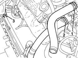
1. Loosen the band and disconnect the radiator upper coolant inlet hose, thermostat side and remove it.
2. Loosen the band and disconnect the radiator lower coolant inlet hose, radiator side.
3. Loosen the band and disconnect the intermediate coupling for the engine cooling system supply pipe.
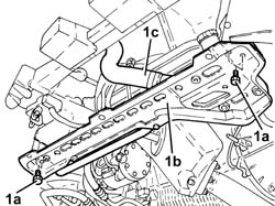
1. Undo the bolts (1a) and remove the lower radiator crossmember (1b) complete with engine cooling system pipes (1c).
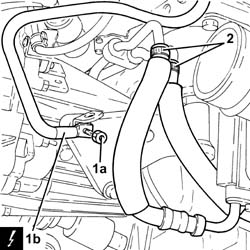
1. Undo the nut (1a) and disconnect the earth lead (1b) from the gearbox side power unit rigid support.
| Description | Connector | |
|---|---|---|
| 1b | Battery earth | See C1 BATTERY EARTH |
2. Loosen the bands and disconnect the flexible power assisted steering fluid supply and return pipes to the radiator, rigid pipe side.
Collect the power assisted steering hydraulic circuit fluid that comes out in a suitable container.
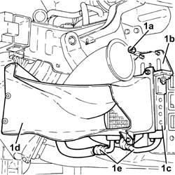
1. Undo the nuts (1a) and remove the power assisted steering system fluid cooling radiator mounting bracket (1b) complete with radiator (1c), duct (1d) and piping (1e).
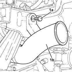
1. Undo the bolt (1a) and remove the cold air intake for the air filter (1b).
1. Undo the connector (1a) and disconnect the supply pipe from the pump to the power assisted steering box (1b), power assisted steering box side.
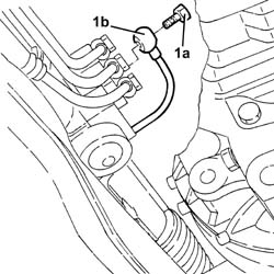
1. Loosen the band and disconnect the intermediate coupling for the return pipe from the power assisted steering box to the radiator.
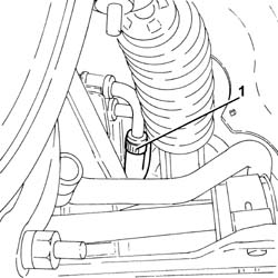
Proceed with the removal
Op. 1076B82 LEFT EXHASUST PIPE BETWEEN CATALYTIC PRECONVERTER AND CONVERTER R R.
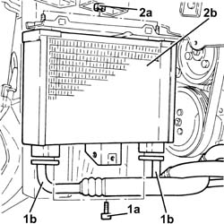
1. Undo the bolts (1a) and disconnect the engine oil inlet and outlet pipes (1b), engine oil cooling radiator side.
Collect the engine oil in a suitable container.
2. Undo the nuts (2a) and remove the engine oil cooling radiator (2b).
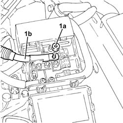
1. Undo the nut (1a) and disconnect the starter motor electrical connection (1b) from the maxi fuse box.
1. Disconnect the electrical connection from the reversing light switch.
| Description | Connector | |
|---|---|---|
| 1 | Reversing lights switch | See I20 REVERSING LIGHTS SWITCH |
2. Disconnect the gear selector and engagement cables.
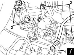
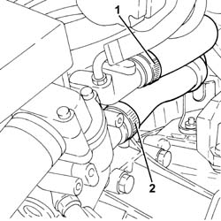
1. Loosen the collar and disconnec the coolant delivery pipe to the climate control system heater, connector side.
2. Loosen the band and disconnect the coolant return pipe from the climate control system heater, thermostat side.
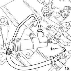
Remove the protective cap from the bleed valve on the clutch operating cyliner.
Connect the recovery device (pipe and reservoir) to the bleed valve on the operating cylinder.
Operate the clutch pedal until the brake/clutch reservoir is drained.
1. Remove the split pin (1a) and disconnect the pipe from the vibration damper to the clutch operating cylinder (1b), damper side.
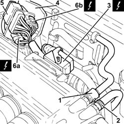
1. Disconnect the rapid connector for the fuel vapour recirculation pipe from the air chamber.
2. Loosen the band and disconnect the brake servo vacuum intake pipe from the air chamber.
3. Disconnect the electrical connection from the injection/ignition control unit.
| Description | Connector | |
|---|---|---|
| 3 | Engine management control unit | See M10 ENGINE MANAGEMENT ECU |
4. Open the electrical connection holder case.
5. Disconnect the engine coupling.
6. Disconnect the electrical connections (6a) and (6b) securing the rear Lambda sensors to the catalytic converter.
| Description | Connector | |
|---|---|---|
| 6a | Lambda sensor on catalyzer | See K17 LAMBDA SENSOR ON CATALYZER ( CONNECTORS ) |
| Description | Connector | |
|---|---|---|
| 6b | Lambda sensor on catalyzer - 2 | See K18 LAMBDA SENSOR ON CATALYZER 2 ( CONNECTORS ) |
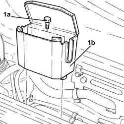
1. Undo the bolts (1a) and remove the electrical connections box (1b).
1. Loosen the coolar and disconnect the coolant return pipe from the engine coolant reservoir.
2. Undo the bolts (2a) and remove the power unit reaction rod (2b).
Discharge the fuel supply pressure.
1. Disconnect the fuel supply pipe rapid connector.
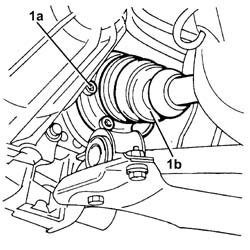
1. Undo the bolts (1a) and disconnect the right driveshaft (1b) from the intermediate driveshaft.
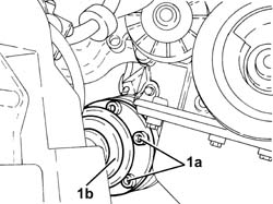
1. Undo the bolts (1a) and disconnect the left driveshaft (1b) from the differential internal shaft.
Proceed with the removal
Op. 1008A44 REAR RIGID MOUNT - R R.
Postion a suitable footboard beneath the power unit.
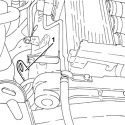
1. Fit a suitable bracket on the left cylinder head for supporting the power unit.
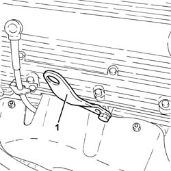
1. Fit a suitable bracket on the right cylinder head for supporting the power unit.
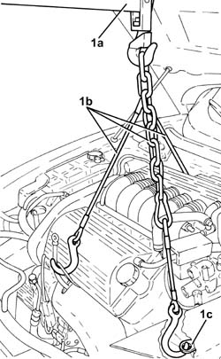
1. Using a hydraulic hoist (1a) fitted with suitable chains (1b) connected to the brackets fitted previously and to the bracket (1c) already on the gearbox, support the power unit.
1. Unscrew the bolt securing the power unit rigid mount to the flexible block.
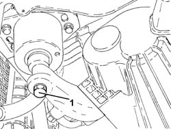
1. Loosen the nut fixing the timing side rigid engine support to the flexible mounting.
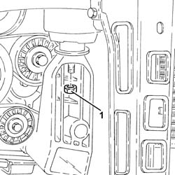
Move the power unit foward to prevent interference with the front suspension crossmember, then slowly lower the power unit using the hydraulic hoist until it is resting on the support positioned previously.
Refitting
Replace the power unit in the engine compartment using a hydraulic hoist.
1. Tighten the nut fixing the timing side rigid engine support to the flexible mounting.
| Fastening | Component | Ø | Value (daNm) | |
|---|---|---|---|---|
| 1 | Nut | RIGID ENGINE MOUNT, TIMING SIDE | M10 | (Flexible mounting side) 4.5 - 5.5 |
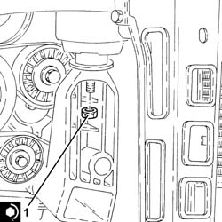
1. Tighten the bolt securing the gearbox side power unit rigid support to the flexible mounting.
| Fastening | Component | Ø | Value (daNm) | |
|---|---|---|---|---|
| 1 |
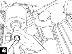
Remove the hydraulic hoist with the chains used to support the power unit.
Remove the brackets fitted for supporting the power unit.
Remove the support positioned previously underneath the power unit.
Proceed with the refitting
Op. 1008A44 REAR RIGID MOUNT - R R.
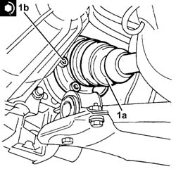
1. Connect the left driveshaft (1a) to the differential internal shaft and secure it tightening the bolts (1b) to the recommended torque.
| Fastening | Component | Ø | Value (daNm) | |
|---|---|---|---|---|
| 1b |
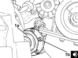
1. Connect the right driveshaft (1a) to the intermediate driveshaft and secure it tightening the bolts (1b) to the recommended torque.
| Fastening | Component | Ø | Value (daNm) | |
|---|---|---|---|---|
| 1b |
Connect the fuel supply pipe rapid connector.
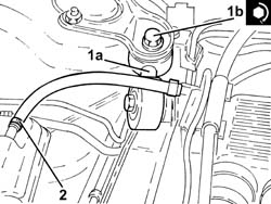
1. Place the power unit reaction rod (1a) in its housing and secure it tightening the bolts (1b) to the recommended torque.
| Fastening | Component | Ø | Value (daNm) | |
|---|---|---|---|---|
| 1b | Bolt | POWER UNIT REACTION ROD | M10 | 4.5 ÷ 5.5 |
2. Connect the coolant return pipe to the engine coolant reservoir to the coolant reservoir and tighten the band.
Place the electrical connections box in its housing and secure it using the bolts.
Connect the electrical connections for the rear Lambda sensors to the catalytic converter.
Connect the engine coupling.
Close the electrical connection holder case.
Connect the electrical connection to the injection/ignition control unit.
Connect the brake servo vacuum intake pipe to the air chamber and tighten the band.
Connect the rapid connector for the fuel vapour recirculation pipe to the air chamber.
Connect the pipe from the vibration damper to the clutch operating cylinder, damper side and secure it using the split pin.
Connect the coolant return pipe from the climate control system heater, thermostat side, and tighten the band.
Connect the coolant supply pipe to the climate control system heater, connector side, and tighten the band.
Connect the gear selector and engagement cables.
Connect the electrical connection to the reversing light switch.
Connect the starter motor electrical connection to the maxi fuse box and tighten the nut.
Place the engine oil cooling radiator back in its housing and tighten the nuts.
Connect the engine oil inlet and outlet pipes, engine cooling radiator side and tighten the bolts.
Proceed with the refitting
Op. 1076B82 LEFT EXHASUST PIPE BETWEEN CATALYTIC PRECONVERTER AND CONVERTER R R.
Connect the intermediate coupling for the return pipe from the power assisted steering box to the radiator and tighten the band.
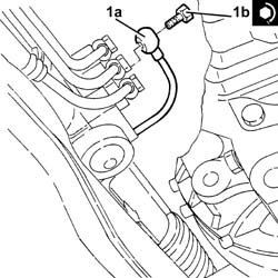
1. Connect the supply pipe from the pump to the power assisted steering box (1a), power assisted steering box side and tighten the connector (1b) to the recommended torque.
| Fastening | Component | Ø | Value (daNm) | |
|---|---|---|---|---|
| 1b | Connector | PIPE BTWN PUMP + POWER STEERING BOX | M14 | (Power assisted steering box side) 3.6 - 4.4 |
Place the cold air intake for the air filter back in its housing and secure it using the bolt.
Place the power assisted steering system fluid cooling radiator mounting bracket in position complete with radiator, duct and piping and secure it using the nuts.
Connect the flexible power assisted steering fluid supply and return pipes to the radiator, rigid pipe side and tighten the bands.
Connect the earth lead to the power unit gearbox side rigid support and secure it using the nut.
Place the lower radiator crossmember in position complee with engine cooling system pipes and secure it using the bolts.
Connect the intermediate coupling for the engine cooling system supply pipe and tighten the band.
Connect the radiator lower coolant inlet hose, thermostat side, and tighten the band.
Place the radiator upper coolant inlet hose in position, connect it to the thermostat and tighten the band.
Proceed with the refitting
Op. 1088B20 ENGINE COOLING RADIATOR - R + R.
Proceed with refitting - 7210A15 R&R FRONT WING/HEADLAMP HOUSING CROSSMEMBER
Proceed with the refitting
Op. 7025A34 BONNET LID LOCK (ONE) - R+R OR REPAIR.
Proceed with the refitting
Op. 5540B76 FRONT LIGHT CLUSTER WITH FOGLAMP ONE LH OR RH R R WITH INTERFERING PARTS REMOVED
(Right and left sides).
Proceed with the refitting
Op. 7210E10 R.R. FRONT BUMPER.
Proceed with the refitting
Op. 7055B42 LH OR RH REFLECTOR(ONE) ON REAR BUMPERS - R R.
Proceed with the refitting
Op. 7055B64 LH OR RH REFLECTOR(ONE) ON REAR BUMPERS - R R.
Proceed with the refitting
Op. 4450B12 FRONT OR REAR WHEELS (TWO) - R+R.
Proceed with the refitting
Op. 1048A10 AIR CLEANER FILTERING ELEMENT - REPLACE.
Proceed with the refitting
Op. 5530B52 BATTERY DRIP TRAY/SUPPORT - R.R..
Proceed with the refitting
Proceed with the refitting
Op. 1048A48 THROTTLE HEATER SLEEVE - R R.
Refill the engine oil lubrication system
Op. 0010T11 ENGINE OIL CHECK LEVEL AND TOP UP.
Refill the engine cooling system
Op. 0010T20 COOLANT CHECK DENSITY AND TOP UP IF NECESSARY.
Bleed the air and top up the hydraulic clutch release system
Op. 0010T67 HYDRAULIC CLUTCH SYSTEM BLEED AIR.
Refill the air conditioning refrigerant circuit
Op. 5040A10 EXPANSION/CONNECTION PIPE - R R.
Refill the power assisted steering circuit with the recommended fluid.
| Type | Component | Description | Qty. | |
|---|---|---|---|---|
| Fluid [I] | POWER STEERING HYDRAULIC SYSTEM | TUTELA GI/A | 1.2 |
The table shows the total quantity of fluid present in the power steering circuit.
Proceed with bleeding the air from the power assisted steering system following the instructions given below.
With the front wheels raised off the ground and the engine switched off, carry out 4 or 5 complete rotations of the steering wheel (left and right).
Check the level of the fluid in the reservoir and top up if necessary.
Remove the vehicle from the lift.
Start the engine and carry out 4 - 5 complete steering wheel rotation cycles (left and right).
Top up the fluid level in the reservoir.
Proceed with the refitting
Op. 7055B54 UNDER-ENGINE GUARD - R R.
Removing
Position the vehicle on a lift.
Proceed with removal - 1016A10 SOUNDPROOFING COVER - R&R.
Drain the air conditioning refrigerant circuit
Op. 0010T84 COOLANT FOR AIR CONDITIONING SYSTEM DEHYDRATE AND RECHARGE.
Proceed with the removal
Op. 4450B12 FRONT OR REAR WHEELS (TWO) - R+R.
Proceed with the removal
Op. 7055B54 UNDER-ENGINE GUARD - R R.
Proceed with the removal
Op. 7055B64 LH OR RH REFLECTOR(ONE) ON REAR BUMPERS - R R.
Proceed with the removal
Op. 7055B42 LH OR RH REFLECTOR(ONE) ON REAR BUMPERS - R R.
Proceed with the removal
Op. 7210E10 R.R. FRONT BUMPER.
Proceed with the removal
Op. 1084C40 CONVOGLIATORE ARIA PER RADIATORE RAFFREDDAMENTO OLIO MOTORE - S.R..
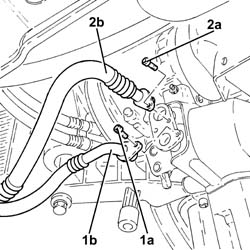
1. Undo the bolt (1a) and disconnect the engine oil supply pipe to the cooling radiator (1b), engine oil filter mounting side.
2. Undo the bolt (2a) and disconnect the engine oil return pipe from the cooling radiator (2b), engine oil filter mounting side.
Collect the engine oil that comes out in a suitable container.
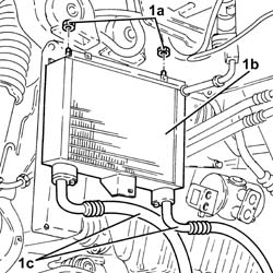
1. Undo the nuts (1a) and remove the engine oil cooling radiator (1b) complete with pipes (1c).
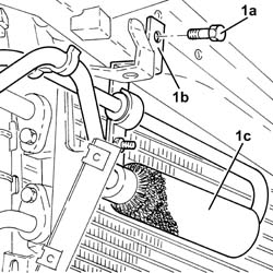
1. Undo the bolt (1a) and move the bracket (1b) to the side complete with power assisted steering system heat exchanger pipe (1c).
Proceed with the removal
Proceed with the removal
Op. 5530B52 BATTERY DRIP TRAY/SUPPORT - R.R..
1. Loosen the band and disconnect the lower coolant inlet hose from the radiator, water pump rigid coolant inlet pipe side.
Collect the coolant in a suitable container.
2. Loosen the band and disconnect the system supply pipe, water pump rigid inlet pipe side.
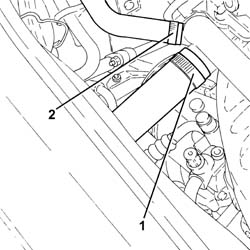
1. Loosen the band and disconnect the upper radiator coolant inlet hose, thermostat side.
2. Loosen the band and disconnect the climate control system heater coolant supply pipe, thermostat side.
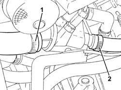
1. Loosen the band and disconnect the coolant outlet pipe from the climate control system heater, water pump rigid inlet pipe side.
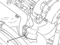
1. Loosen the band and disconnect the flexible pipe from the coolant rigid return pipe to the engine coolant reservoir.
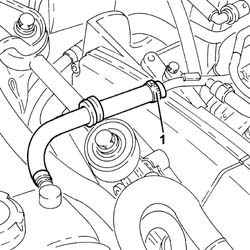
1. Loosen the band and disconnect the air inlet hose from the connector on the throttle casing.
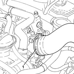
1. Undo the bolts (1a) and move the bracket (1b) complete with turbocharger vane position actuator solenoid valve (1c) away from the air filter.
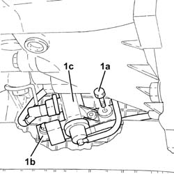
1. Undo the bolt fixing the cold air intake to the upper radiator crossmember.
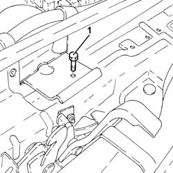
1. Loosen the band (1a) and remove the cold air intake (1b).
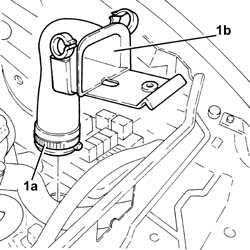
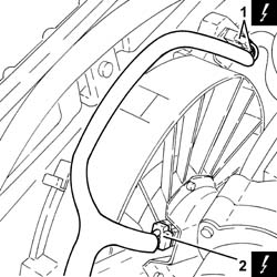
1. Disconnect the electrical connection from the air flow meter.
| Description | Connector | |
|---|---|---|
| 1 | Air flow meter | Vedere K41 MISURATORE PORTATA ARIA ( ANTERIORE ) |
2. Loosen the band securing the corrugated hose to the air flow meter.
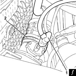
1. Disconnect the electrical connections for the engine cooling fan resistor.
| Description | Connector | |
|---|---|---|
| 1 | Engine fan adjustment resistance | See O10 ENGINE FAN ADJUSTMENT RESISTOR - 1 |
2. Disconnect the electrical connection from the engine fan motor and move the electrical wiring sideways.
| Description | Connector | |
|---|---|---|
| 2 | Engine fan motor | See N11 ENGINE FAN MOTOR - 1 |
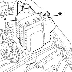
1. Remove the air filter (1a) complete with air flow meter (1b).
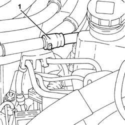
1. Disconnect the rapid connector for the brake servo vacuum pipe.
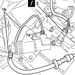
Remove the protective cap from the bleed valve on the clutch operating cyliner.
Connect the recovery device (pipe and reservoir) to the bleed valve on the operating cylinder.
Operate the clutch pedal until the brake/clutch reservoir is drained.
1. Undo the connector (1a) and disconnect the pipe from the vibration damper to the clutch operating cylinder (1b), operating cylinder side.
2. Disconnect the electrical connection from the reversing light switch.
| Description | Connector | |
|---|---|---|
| 2 | Reversing lights switch | See I20 REVERSING LIGHTS SWITCH |
1. Disconnect the gear selector and engagement cables.
2. Undo the fastenings and move the mounting bracket aside complete with gear selection and engagement cables.
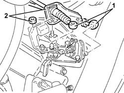
1. Undo the nuts (1a) and lift up the heater plugs control unit (1b) as necessary.
2. Disconnect the electrical connection from the heater plugs from the control unit.
| Description | Connector | |
|---|---|---|
| 2 | Heater plugs control unit | See M15 PLUG PREHEATING CONTROL UNIT |
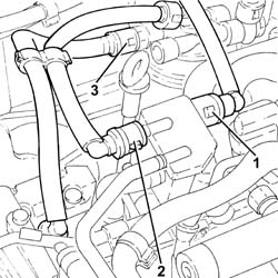
1. Disconnect the rapid connector for the fuel return pipe to the tank, fuel return manifold pipe side.
2. Disconnect the rapid connector for the fuel return pipe from the fuel filter, fuel return manifold pipe side.
3. Disconnect the rapid connector for the fuel supply pipe to the pressure pump, fuelf filter side.
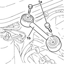
1. Undo the bolts (1a) and remove the power unit reaction rod (1b).
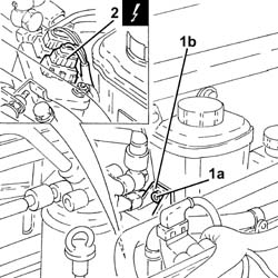
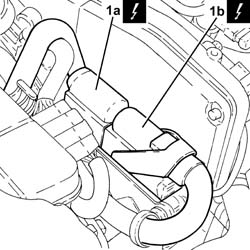
1. Disconnect the electrical connections (1a) and (1b) from the diesel electronic injection system control unit.
| Description | Connector | |
|---|---|---|
| 1a | Engine management control unit | Vedere M10A CENTRALINA CONTROLLO MOTORE ( ANTERIORE ) |
| Description | Connector | |
|---|---|---|
| 1b | Engine management control unit | See M10B ENGINE MANAGEMENT CONTROL UNIT ( CONNECTORS ) |
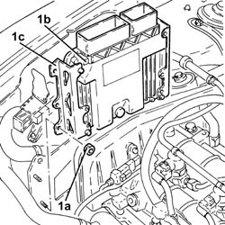
1. Undo the nuts (1a) and remove the diesel electronic injection system control unit (1b) complete with guides (1c).
Remove the power assisted steering fluid reservoir cap and draw off the fluid using a suitable syringe.
Place the power assisted steering fluid cap in position.
1. Undo the bolts fixing the power assited steering fluid reservoir.
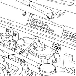
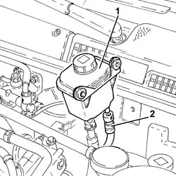
1. Move the power assisted steering fluid reservoir away positioning it as illustrated.
2. Disconnect the rapid connector for the supply pipe from the fluid reservoir to the power assisted steering pump, reservoir side.
1. Undo the connector (1a) and disconnect the supply pipe from the pump to the power assisted steering box (1b), power assisted steering box side.
2. Release the supply pipe from the pump to the power assisted steering box from the fastening bands on the power assisted steering box.
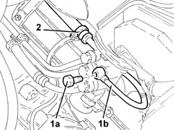
1. Undo the bolt (1a) and disconnect the coolant inlet/outlet pipes flange (1b) from the air conditioning compressor.
2. Undo the nut (2a) and disconnect the intermediate coupling for the pipe from the air conditioning compressor to the evaporator (2b).
Seal the connectors that have been disconnected using suitable plugs to prevent dampness and impurities from entering the system.
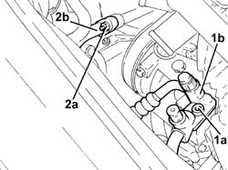
1. Undo the bolts (1a) and disconnect the coolant inlet/outlet pipes (1b) from the air conditioning condenser.
Seal the connectors that have been disconnected using suitable plugs to prevent dampness and impurities from entering the system.
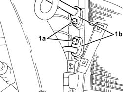
1. Undo the upper bolt fixing the engine cooling radiator to the upper crossmember.
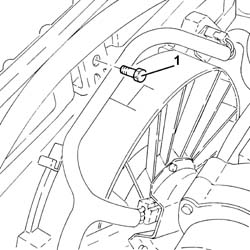
1. Loosen the bands (1a) and remove the air supply hose between the turbocharger and the heat exchanger (1b).
2. Disconnect the earth lead from the gearbox.
| Description | Connector | |
|---|---|---|
| 2 | Battery earth | See C1 BATTERY EARTH |
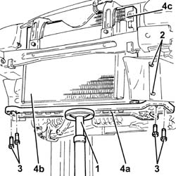
1. Position a hydraulic jack under the lower radiator crossmember.
2. Release the two buttons fastening the air duct on the supercharging air/air heat exchanger to the engine cooling radiator duct.
3. Unscrew the bolts securing the lower radiator crossmember to the bodyshell.
4. Lower the hydraulic jack and remove the lower radiator crossmember (4a), the climate control system condenser (4b), the engine cooling radiator (4c) and the fan.
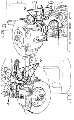
1. Loosen the bands fixing the driveshaft boots to the differential internal driveshaft/intermediate driveshaft.
2. Release the front brake caliper flexible pipes, the electrical wiring for the pad wear sensor and the electrical wiring for the wheel rpm sensors (A.B.S.) from the fastenings.
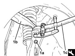
1. Undo the nut (1a) and disconnect the front track control arms from the steering knuckles using the tool (1c).
| Description | Code | |
|---|---|---|
| 1c | Extractor | 1.821.169.000 |
Move the driveshafts away from the differential internal driveshaft/intermediate driveshaft.
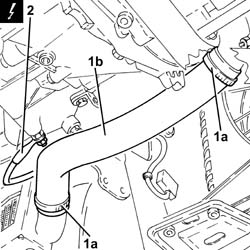
Proceed with the removal
Op. 1076B70 EXHAUST PIPE BETWEEN PRE-CATALYTIC CONVERTER AND CATALYTIC CONVERTER - R R.
Proceed with the removal
Op. 1008A44 REAR RIGID MOUNT - R R.
Postion a suitable footboard beneath the power unit.
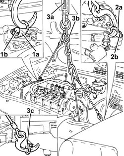
1. Fit the bracket (1a) and secure it as illustrated to the bracket on the engine for the reaction using the bolt (1b).
2. Fit the bracket (2a) and fasten it to the gearbox as illustrated using the bolt (2b).
3. Using a hydraulic hoist (3a) fitted with suitable chains (3b) connected to the brackets fitted previously and to the bracket (3c) already on the gearbox, support the power unit.
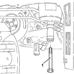
1. Loosen the bolt fixing the timing side rigid engine support to the flexible mounting.
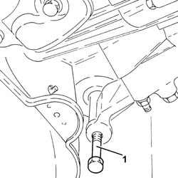
1. Unscrew the bolt securing the power unit rigid mount to the flexible block.
Slowly lower the power unit with the hydraulic hoist until it rests on the board positioned previously.
Take great care during the removal of the power unit not to damage the components fitted on the vehicle and, in particular, check that the gearbox-differential unit does not impact against the A.B.S. assembly.
Refitting
Replace the power unit in the engine compartment using a hydraulic hoist.
1. Tighten the bolt securing the gearbox side power unit rigid support to the flexible mounting.
| Fastening | Component | Ø | Value (daNm) | |
|---|---|---|---|---|
| 1 |
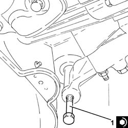
1. Tighten the bolt fixing the timing side rigid engine support to the flexible mounting.
| Fastening | Component | Ø | Value (daNm) | |
|---|---|---|---|---|
| 1 | Bolt | RIGID ENGINE MOUNT, TIMING SIDE | M12 | (Flexible mounting side) 7.9 - 9.7 |
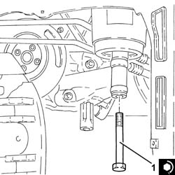
Remove the hydraulic hoist with the chains used to support the power unit.
Remove the brackets fitted for supporting the power unit.
Remove the support positioned previously underneath the power unit.
Proceed with the refitting
Op. 1008A44 REAR RIGID MOUNT - R R.
Proceed with the refitting
Op. 1076B70 EXHAUST PIPE BETWEEN PRE-CATALYTIC CONVERTER AND CATALYTIC CONVERTER - R R.
Place the driveshafts in their housings in contact with the differential internal driveshaft/intermediate driveshaft.
1. Connect the upper track control arms (1a) to the steering knuckles and secure them tightening the nuts (1b) to the recommended torque.
| Fastening | Component | Ø | Value (daNm) | |
|---|---|---|---|---|
| 1b | Nut | UPPER FRONT TRACK CONTROL ARMS | M10 | (Steering knuckle) 4.3 - 4.7 |
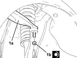
Tighten the bands fixing the driveshaft boots to the differential internal driveshaft/intermediate driveshaft.
Fasten the front brake caliper flexible pipes, the electrical wiring for the pad wear sensors and the A.B.S. sensors electrical wiring.
Connect the earth lead to the gearbox.
Place the air supply hose between the turbocharger and the heat exchanger in position and tighten the bands.
Place the lower radiator crossmember in its housing using the hydraulic jack complete with climate control system condenser, engine cooling radiator and fan.
Tighten the bolts securing the lower radiator crossmember to the bodyshell.
Remove the hydraulic jack from underneath the lower radiator crossmember.
Fit the two buttons fastening the air duct on the supercharging air/air heat exchanger to the engine cooling radiator duct.
Tighten the upper bolt fixing the engine cooling radiator to the upper crossmember.
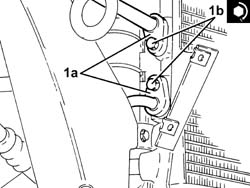
1. Connect the coolant fluid inlet and outlet pipes (1a) to the air conditioning condenser and tighten the bolts (1b) to the recommended torque.
Replace any O-Rings for the connectors using green coloured seals only which are resistant to the R134a refrigerant fluid.
Lubricate the connector threads using anti-freeze..
| Fastening | Component | Ø | Value (daNm) | |
|---|---|---|---|---|
| 1b | Bolt | COOLANT SYSTEM FITTINGS | M6 | 0.7 ÷ 1.1 |
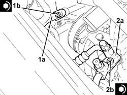
1. Connect the intermediate coupling for the pipe from the air conditioning compressor to the evaporator (1a) and tighten the nut (1b) to the recommended torque.
Replace any O-Rings for the connectors using green coloured seals only which are resistant to the R134a refrigerant fluid.
Lubricate the connector threads using anti-freeze..
| Fastening | Component | Ø | Value (daNm) | |
|---|---|---|---|---|
| 1b | Nut | COOLANT SYSTEM FITTINGS | M6 | 0.7 ÷ 1.1 |
2. Connect the flange for the coolant inlet/outlet pipes (2a) to the air conditioning compressor and tighten the bolt (2b) to the recommended torque.
| Fastening | Component | Ø | Value (daNm) | |
|---|---|---|---|---|
| 2b | Bolt | COOLANT SYSTEM FITTINGS | M10 | (Compressor side) 3.2 - 3.9 |
1. Secure the supply pipe from the pump to the power assisted steering box to the fastening bands on the power assisted steering box.
2. Connect the supply pipe from the pump to the power assisted steering box (2a), power assisted steering box side and tighten the connector (2b) to the recommended torque.
| Fastening | Component | Ø | Value (daNm) | |
|---|---|---|---|---|
| 2b | Connector | PIPE BTWN PUMP + POWER STEERING BOX | M14 | (Power assisted steering box side) 3.6 - 4.4 |
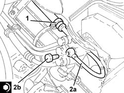
Connect the rapid connector for the supply pipe from the fluid reservoir to the power assisted steering pump, reservoir side.
Place the power assisted steering fluid reservoir in its housing and secure it using the bolts.
Place the control unit for the diesel electronic injection system complete with guides in its housing and secure it using the nuts.
Connect the electrical connections to the diesel electronic injection system control unit.
1. Place the power unit reaction rod (1a) in its housing and secure it tightening the bolts (1b) to the recommended torque.
| Fastening | Component | Ø | Value (daNm) | |
|---|---|---|---|---|
| 1b | Bolt | POWER UNIT REACTION ROD | M10 | 4.5 ÷ 5.5 |
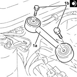
Connect the rapid connector for the fuel supply pipe to the pressure pump, fuel filter side.
Connect the rapid connector for the fuel return pipe from the fuel filter, fuel return manifold pipe side.
Connect the rapid connector for the fuel return pipe to the tank, fuel return manifold pipe side.
Connect the electrical connection to the heater plugs from the control unit.
Place the heater plugs control unit in position and secure it using the nuts.
Place the mounting bracket in position complete with gear selection and engagement cables and secure it.
Connect the gear selector and engagement cables.
Connect the electrical connection to the reversing light switch.
Connect the pipe from the vibration damper to the operating cylinder, operating cylinder side and tighten the connector to the recommended torque.
| Fastening | Component | Ø | Value (daNm) |
|---|
Connect the rapid connector for the brake servo vacuum pipe.
Refit the air filter with air flow meter in its seat.
Place the electrical wiring back in its housing, then connect the electrical connection to the engine fan motor.
Connect the electrical connections to the engine cooling fan resistor.
Tighten the band securing the corrugated hose to the air flow meter.
Connect the electrical connection to the air flow meter.
Place the cold airintake back in its housing and tighten the band.
Tighten the bolt fixing the cold air intake to the crossmember.
Place the bracket complete with turbocharger vane position actuator solenoid valve and secure it using the bolts.
Connect the air inlet hose to the connector on the throttle casing and tighten the band.
Connect the flexible pipe to the engine coolant reservoir rigid coolant return pipe and tighten the band.
Connect the coolant outlet pipe from the climate control system heater, water pump rigid inlet pipe side.
Connect the coolant delivery pipe to the climate control system heater, thermostat side, and tighten the band.
Connect the upper coolant input sleeve to the radiator, thermostat side, and tighten the band.
Connect the system supply pipe, water pump rigid inlet side and tighten the band.
Connect the lower coolant inlet hose from the radiator, water pump rigid coolant inlet pipe side and tighten the band.
Proceed with the refitting
Op. 5530B52 BATTERY DRIP TRAY/SUPPORT - R.R..
Proceed with the refitting
Place the bracket complete with power assisted steering system heat exchanger pipe in osition and secure it using the bolt.
Place the engine oil cooling radiator complete with pipes back in its housing and tighten the nuts.
Connect the engine oil return pipe from the cooling radiator, engine oil filter mounting side and tighten the bolt.
Connect the engine oil supply pipe to the cooling radiator, engine oil filter mounting side and tighten the bolt.
Proceed with the refitting
Op. 1084C40 CONVOGLIATORE ARIA PER RADIATORE RAFFREDDAMENTO OLIO MOTORE - S.R..
Proceed with the refitting
Op. 7210E10 R.R. FRONT BUMPER.
Proceed with the refitting
Op. 7055B42 LH OR RH REFLECTOR(ONE) ON REAR BUMPERS - R R.
Proceed with the refitting
Op. 7055B64 LH OR RH REFLECTOR(ONE) ON REAR BUMPERS - R R.
Proceed with the refitting
Op. 7055B54 UNDER-ENGINE GUARD - R R.
Proceed with the refitting
Op. 4450B12 FRONT OR REAR WHEELS (TWO) - R+R.
Refill the engine oil lubrication system
Op. 0010T11 ENGINE OIL CHECK LEVEL AND TOP UP.
Refill the engine cooling system
Op. 0010T20 COOLANT CHECK DENSITY AND TOP UP IF NECESSARY.
Proceed with the refitting
Op. 0010T67 HYDRAULIC CLUTCH SYSTEM BLEED AIR.
Refill the air conditioning refrigerant circuit
Op. 0010T84 COOLANT FOR AIR CONDITIONING SYSTEM DEHYDRATE AND RECHARGE.
Refill the power assisted steering circuit
Op. 0010T71 POWER STEERING FLUID CHECK LEVEL AND TOP UP IF NECESSARY.
Proceed with refitting - 1016A10 SOUNDPROOFING COVER - R&R.
Remove the vehicle from the lift.
Removing
- Position the vehicle on a lift.
- Op. 5530B10 BATTERIA - S.R.
During the removal of the battery, take care to also disconnect the starter motor supply cable, shown in the diagram, from the maxi fuse box.
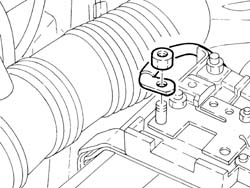
- Op. 5530B52 SUPPORTO/CESTELLO BATTERIA - S.R.
1. Disconnect the earth lead from the power unit gearbox side rigid support.
| Description | Connector | |
|---|---|---|
| 1 | Earth on engine | Vedere C40 MASSA SU MOTORE |
2. Disconnect the electrical connection from the reversing light switch.
| Description | Connector | |
|---|---|---|
| 2 | Reversing lights switch | Vedere I20 INTERRUTTORE LUCI RETROMARCIA |
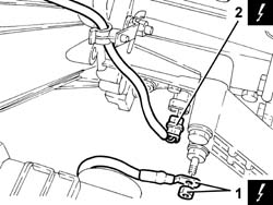
1. Disconnect the electrical connection from the air flow meter.
| Description | Connector | |
|---|---|---|
| 1 | Air flow meter | Vedere K41 MISURATORE PORTATA D''ARIA |
- Release the electrical wiring for the air flow meter from the fastening on the air intake hose.
2. Disconnect the oil vapour recirculation pipe from the air intake hose.
3. Disconnect the air intake hose from the throttle casing.
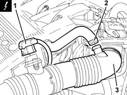
- Remove the air filter assembly and intake hose complete with air flow meter after having released it from the resonator unit.
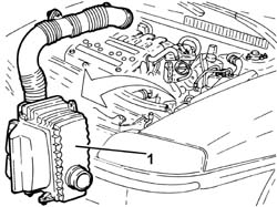
- Move the rubber protection aside to access the coupling for the clutch hydraulic actuator pipe.
- Completely release the flexible clip retaining the pipe to the actuator body.
- Disconnect the flexible pipe from the vibration damper to the clutch hydraulic actuator, hydraulic actuator side and secure it.
Collect the clutch fluid that comes out in a suitable container, then seal the pipe and place it at the side.
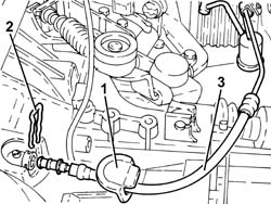
1. Disconnect the gear selector and engagement cables.
To disconnect the gear selector cable, press the release tabs illustrated and retract the actual cable.
2. Remove the plates (2a) and release the gear selector and engagement cables from the mounting bracket (2b).
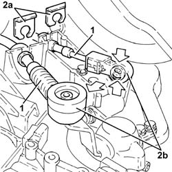
- Disconnect the brake servo single-acting valve, brake servo side.
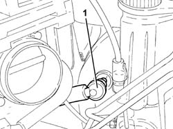
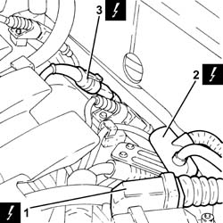
1. Disconnect the electrical connection from the injection/ignition control unit.
| Description | Connector | |
|---|---|---|
| 1 | Engine management control unit | Vedere M10 CENTRALINA CONTROLLO MOTORE |
2. Disconnect the engine front coupling.
| Description | Connector | |
|---|---|---|
| 2 | Front/engine coupling | Vedere D4 GIUNZIONE ANTERIORE/MOTORE |
3. Disconnect the electrical connection for the Lambda sensor.
| Description | Connector | |
|---|---|---|
| 3 | Lambda sensor on pre-catalyzer | Vedere K15 SONDA LAMBDA SUL PRE-CATALIZZATORE |
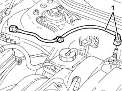
- Disconnect the rapid connectors and remove the fuel vapour recovery pipe.
Seal the fuel vapour recovery system pipes.
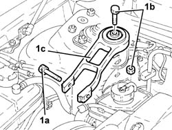
- Undo the bolt (1a), bolt (1b) and remove the power unit reaction rod (1c).
- Draw off the power assisted steering fluid from the reservoir using a suitable syringe.
- Undo and remove the engine oil filler plug.
- Undo the bolts (2a) and remove the ignition coils cover (2b).
- Place the engine oil filler cap in its housing.
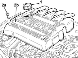
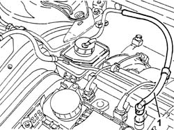
- Discharge the fuel supply pressure with the tool connected to the special valve located at the side of the fuel manifold pipe.
| Description | Code | |
|---|---|---|
| Connector | 1.870.684.000 |
- Disconnect the rapid connector for the front fuel supply pipe, fuel manifold pipe side.
Seal the front fuel supply pipe and place it at the side.
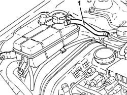
- Disconnect the coupling for the coolant return pipe from the engine coolant reservoir.
Seal the disconnected pipes to prevent impurities from getting into the system.
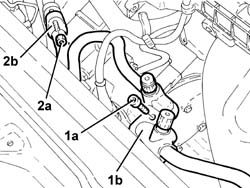
- Undo the bolt (1a) and disconnect the coolant inlet/outlet pipes flange (1b) from the air conditioning compressor.
- Undo the nut (2a) and disconnect the flange (2b) for the pipe from the air conditioning condenser to the intermediate connector, intermdiate connector side.
Seal the connectors that have been disconnected using suitable plugs to prevent dampness and impurities from entering the system.
- Op. 4450B12 RUOTE (DUE) ANTERIORI - S.R.
- Op. 7055B65 ENGINGE BAY DUSTGUARD PROTECTION IN LEFT FRONT WHEEL ARCH R R
- Op. 7055B66 ENGINE COMPARTMENT DUST SHIELD PROTECTION IN RIGHT FRONT WHEEL ARCH - R.R.
- Op. 7055B90 LEFT FRONT WHEEL ARCH LINER - R.R.
- Op. 7055B91 RIGHT FRONT WHEEL ARCH LINER - R.R.
- Disconnect the lower coolant outlet hose from the radiator and drain the engine cooling system.
Manually press the clips and release the hose rapid connector.
Collect the coolant in a suitable container.
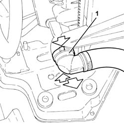
- Disconnect the radiator upper coolant inlet hose.
Manually press the clips and release the hose rapid connector.
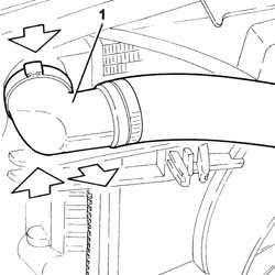
- Release the electrical wiring from the fastening on the engine cooling system supply pipe.
- Disconnect the engine cooling system supply pipe, water pump rigid inlet pipe side.
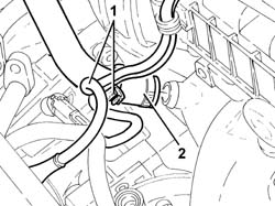
- Disconnect the climate control system heater coolant supply pipe, thermostat side.
- Disconnect the coolant return pipe from the climate control system heater, water pump rigid inlet pipe side.
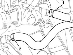
- Unscrew the bolts securing the lower radiator crossmember to the bodyshell.
- Remove the engine cooling radiator complete with fan, air conditioning condenser and pipes and lower crossmember.
Take care to release the fan upper pin from the mounting bracket.
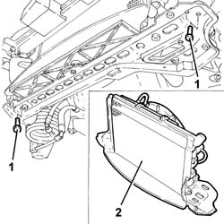
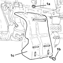
- Undo the nuts (1a) and the bolts (1b), then remove the exhaust manifold heat shield (1c).
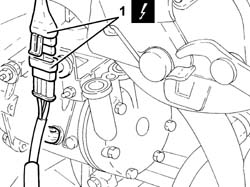
- Disconnect the electrical connection for the right Lambda sensor and release the electrical wiring from the fastenings.
| Description | Code | |
|---|---|---|
| 1 | Lambda sensor | Vedere K40 SONDA LAMBDA |
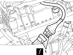
- Disconnect the electrical connection for the left Lambda sensor and release the wiring from the fastenings.
| Description | Code | |
|---|---|---|
| 1 | Lambda sensor - 2 | See K39 LAMBDA SENSOR - 2 |
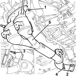
- Undo the nuts fixing the catalytic preconverter to the exhaust manifold.
- Undo the nuts fixing the catalytic preconverter to the catalytic converter.
- Undo the bolts fixing the catalytic preconverter bracket to the engine block.
- Undo the bolt fixing the catalytic preconverter flexible mounting to the front suspension crossmember.
- Remove the catalytic preconverter complete with Lambda sensors.
- Remove the seals.
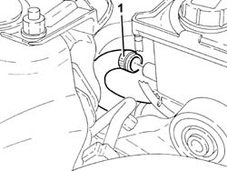
- Disconnect the return pipe from the heat exchanger to the power assisted steering fluid reservoir, reservoir side.
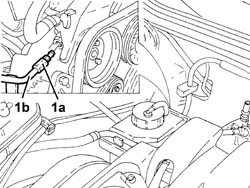
- Undo the connector (1a) and disconnect the supply pipe from the pump to the power assisted steering box (1b), pump side.
- Loosen the bolts fixing the driveshafts to the differential internal driveshaft/intermediate driveshaft.
- Release the front brake caliper flexible pipes, the electrical wiring for the pad wear sensors and the A.B.S. sensors electrical wiring from the fastenings.
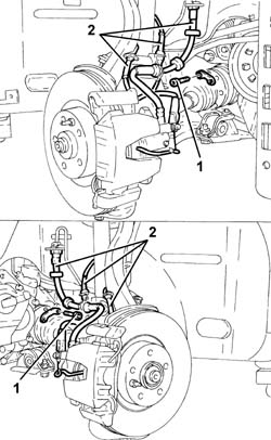
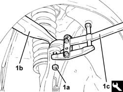
- Undo the nuts (1a) and disconnect the upper front track control arms (1b) from the steering knuckles using the tool (1c).
| Description | Code | |
|---|---|---|
| 1c | Extractor | 1.821.169.000 |
- Move the driveshafts away from the differential internal driveshaft/intermediate driveshaft.
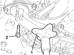
- Position a hydraulic jack under the power unit rigid rear support.
- Unscrew the bolt securing the power unit rigid rear support to the flexible mounting.
- Slowly lower the hydraulic jack and remove it.
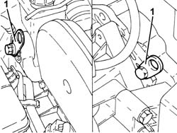
- Postion a suitable footboard beneath the power unit.
- Position suitable brackets on the power unit as illustrated in the diagram.
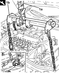
- Support the power unit using a hydraulic hoist (1a) and the tool (1b) connected to the brackets fitted previously.
| Description | Code | |
|---|---|---|
| 1b | Balance | 1.871.001.700 |
- Unscrew the bolt securing the power unit rigid mount to the flexible block.
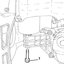
- Loosen the bolt fixing the timing side rigid engine support to the flexible mounting.
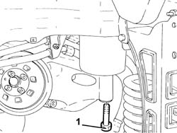
- Slowly lower the power unit with the hydraulic hoist until it rests on the floor.
- Release the hydraulic hoist chains from the power unit.
- Raise the vehicle on the lift.
- Using a hydraulic hoist fitted with suitable chains as described previously, place the power unit on a suitable support.
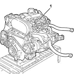
Refitting
- Using a hydraulic hoist fitted with a suitable tool as described previously, position the power unit under the vehicle.
- Release the hydraulic hoist chains from the power unit.
- Lower the vehicle on the lift.
- Via the engine compartment, support the power unit using the hydraulic hoist and the special equipment.
- Slowly raise the power unit using the hydraulic hoist until it is positioned back in its housing in the engine compartment.
- Tighten the bolt securing the timing side rigid engine support to the flexible mounting to the recommended torque.
| Fastening | Component | Ø | Value (daNm) | |
|---|---|---|---|---|
| 1 | Bolt | RIGID ENGINE MOUNT, TIMING SIDE | M12 | (Flexible mounting side) 7.9 - 9.7 |
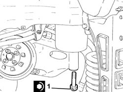
- Tighten the bolt securing the power unit gearbox side rigid support to the flexible mounting to the recommended torque.
| Fastening | Component | Ø | Value (daNm) | |
|---|---|---|---|---|
| 1 | Bolt | GEARBOX SIDE RIGID SUPPORT FOR POWER UNIT | M10 | (Flexible mounting side) 4.2 - 5.1 |
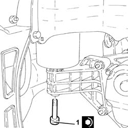
- Remove the tools used for refitting the power unit and put them away.
- Position a hydraulic jack under the power unit rigid rear support and raise it slowly until it is in contact with the flexible mounting.
- Tighten the bolt securing the power unit side rigid rear support to the flexible mounting to the recommended torque.
| Fastening | Component | Ø | Value (daNm) | |
|---|---|---|---|---|
| 2 | Bolt | POWER UNIT REAR RIGID MOUNT | M12 | (Flexible mounting side) 7.5 - 9.2 |
- Remove the hydraulic jack.
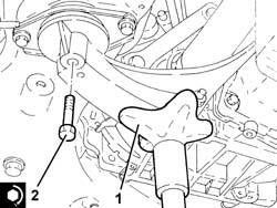
- Place the driveshafts in their housings in contact with the differential internal driveshaft/intermediate driveshaft.
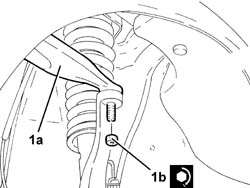
- Connect the upper track control arms (1a) to the steering knuckles and secure them tightening the nuts (1b) to the recommended torque.
| Fastening | Component | Ø | Value (daNm) | |
|---|---|---|---|---|
| 1b | Nut | UPPER FRONT TRACK CONTROL ARMS | M10 | (Steering knuckle) 4.3 - 4.7 |
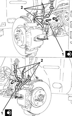
1. Tighten the bolts fixing the driveshafts to the differential internal driveshaft/intermediate driveshaft to the recommended torque.
| Fastening | Component | Ø | Value (daNm) | |
|---|---|---|---|---|
| 1 | Bolt | DRIVESHAFT | M8 | (Differential internal driveshaft/intermediate driveshaft side) 3.5 - 4.3 |
2. Fasten the front brake caliper flexible pipes, the electrical wiring for the pad wear sensors and the A.B.S. sensors electrical wiring.
- Connect the supply pipe from the pump to the power assisted steering box (1a), pump side and tighten the connector (1b) to the recommended torque.
| Fastening | Component | Ø | Value (daNm) | |
|---|---|---|---|---|
| 1b | Connector | PIPE BTWN PUMP + POWER STEERING BOX | M16 | (Power assisted steering pump side) 4.5 - 5.5 |
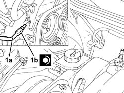
- Connect the return pipe from the heat exchanger to the power assisted steering fluid reservoir, reservoir side.
1. Place the catalytic preconverter back in its housing complete with Lambda sensors and seals.
2. Tighten the bolt fixing the catalytic preconverter flexible mounting to the front suspension crossmember.
3. Tighten the bolts fixing the catalytic preconverter bracket to the engine block.
4. Tighten the nuts fixing the catalytic preconverter to the catalytic converter to the recommended torque.
| Fastening | Component | Ø | Value (daNm) | |
|---|---|---|---|---|
| 4 | Nut | CATALYTIC PRE-CONVERTER | M8 | (Catalytic converter side) 2.7 - 3.3 |
5. Tighten the nuts fixing the catalytic preconverter to the exhaust manifold to the recommended torque.
| Fastening | Component | Ø | Value (daNm) | |
|---|---|---|---|---|
| 5 | Nut | CATALYTIC PRE-CONVERTER | M8 | (Manifold side) 2.7 - 3.3 |
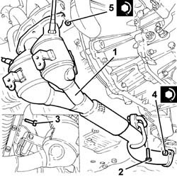
- Connect the electrical connection for the left and right Lambda sensors, then fasten the electrical wiring.
- Place the exhaust manifold heat shield back in its housing and secure it using the nuts and bolts.
- Place the engine cooling radiator complete with fan, air conditioning condenser and pipes and lower crossmember in position.
Check that the fan upper pin is correctly inserted in the mounting bracket.
- Tighten the bolts securing the lower radiator crossmember to the bodyshell.
- Op. 7210E10 R.R. FRONT BUMPER
- Connect the coolant return pipe from the climate control system heater, water pump rigid inlet pipe side.
- Connect the climate control system heater coolant supply pipe, thermostat side.
- Connect the engine cooling system supply pipe, water pump rigid inlet pipe side.
- Connect the upper coolant inlet hose to the radiator.
- Connect the lower radiator coolant outlet hose.
- Op. 7055B90 LEFT FRONT WHEEL ARCH LINER - R.R.
- Op. 7055B91 RIGHT FRONT WHEEL ARCH LINER - R.R.
- Op. 7055B65 ENGINGE BAY DUSTGUARD PROTECTION IN LEFT FRONT WHEEL ARCH R R
- Op. 7055B66 ENGINE COMPARTMENT DUST SHIELD PROTECTION IN RIGHT FRONT WHEEL ARCH - R.R.
- Op. 4450B12 FRONT OR REAR WHEELS (TWO) - R+R
1. Connect the flange for the pipe from the air conditioning condenser to the intermesdiate connector (1a) intermediate connector side and tighten the nut (1b) to the recommended torque.
Replace the O rings for the connectors. Only use green coloured seals that are resistant to R134a refrigerant fluid. Lubricate the connector threads using anti-freeze.
| Fastening | Component | Ø | Value (daNm) | |
|---|---|---|---|---|
| 1b | Nut | COOLANT CIRCUIT CONNECTORS | M6 | 0.7 ÷ 1.1 |
2. Connect the flange (2a) for the air conditioning compressor inlet/supply pipes and secure it by tightening the bolt (2b) to the recommended torque.
| Fastening | Component | Ø | Value (daNm) | |
|---|---|---|---|---|
| 2b | Bolt | COMPRESSOR PIPE CONNECTOR | M10 | (Air conditioning compressor side) 2.8 - 4.2 |
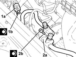
- Connect the coupling for the coolant return pipe from the engine coolant reservoir.
- Connect the rapid connector for the front fuel supply pipe, fuel manifold pipe side.
- Remove the engine oil filler plug.
- Place the ignition coil cover back in its housing and secure it using the bolts.
- Place the engine oil filler cap in its housing.
- Place the power unit reaction link (1a) back in its housing, then secure it by tightening the bolt (1b) and the bolt (1c) to the specified torque.
| Fastening | Component | Ø | Value (daNm) | |
|---|---|---|---|---|
| 1b | Bolt | POWER UNIT REACTION ROD | M10 | (Engine support side) 4.5 - 5.5 |
| Fastening | Component | Ø | Value (daNm) | |
|---|---|---|---|---|
| 1c | Bolt | POWER UNIT REACTION ROD | M10 | (Bodyshell support side) 4.5 - 5.5 |
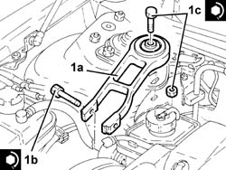
- Place the fuel vapour recovery pipe in position and connect the rapid connectors.
- Connect the electrical connection for the Lambda sensor.
- Connect the engine front coupling.
- Connect the electrical connection to the injection/ignition control unit.
- Connect the brake servo single-acting valve, brake servo side.
- Place the gear selection and engagement cables on the mounting bracket and fasten them using the plates.
- Connect the gear selector and engagement cables.
1. Position the flexible clip as illustrated, i.e. not fully fitted.
Make sure that the housing in the hydraulic actuator for the O-ring and the connector on the pipe is thoroughly clean and in good condition.
Lubricate the O ring with brake fluid, if necessary, to facilitate the fitting of the pipe.
Do not use detergents or mineral lubricants that are not compatible with the materials for the brake fluid.
2. Fully introduce the flexible pipe from the vibration damper to the clutch hydraulic actuator into the clutch hydraulic actuator.
- Insert the flexible clip completely to lock the pipe.
- Place the rubber protection back in its housing.
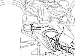
- Place the air filter assembly and intake hose complete with air flow meter in position and connect it to the resonator unit.
- Connect the air intake hose to the throttle casing.
- Connect the oil vapour recirculation pipe to the air intake hose.
- Connect the electrical connection to the air flow meter and secure the electrical wiring to the air intake hose using the band.
- Connect the electrical connection to the reversing light switch.
- Connect the earth lead to the power unit gearbox side rigid support.
- Op. 5530B52 BATTERY DRIP TRAY/SUPPORT - R.R.
- Op. 5530B10 BATTERY - R+R
Take care to also connect the starter motor supply lead to the maxi fuse box.
Parts & tools for this job Staging For 2003 Alfa Romeo GT
- PARTClutch kitSearch: Alfa Romeo GT 2003 clutch kit
- TOOLClutch alignment toolSearch: clutch alignment tool
- FLUIDGear oilSearch: Alfa Romeo GT manual gearbox oil
Links open Amazon search results in a new tab. As an Amazon Associate I earn from qualifying purchases.