
Rear rigid mount - r r
- Make
- Alfa Romeo
- Model
- GT Factory Service Manual
- Year
- 2003–2010
- Section
- Power unit supports › Rear rigid mount - r r
REAR RIGID MOUNT - R R
Removing
Position the vehicle on a lift.
Make sure that the ignition key is in the OFF position, then disconnect the negative battery terminal.
| Description | Connector | |
|---|---|---|
| Battery | See A1B BATTERY ( BATTERY NEGATIVE ) |
Drain the air conditioning refrigerant circuit
Op. 0010T84 COOLANT FOR AIR CONDITIONING SYSTEM DEHYDRATE AND RECHARGE.
Proceed with the removal
Op. 4450B04 RIGHT FRONT WHEEL R R.
Proceed with the removal
Op. 7055B54 UNDER-ENGINE GUARD - R R.
Proceed with the removal
Op. 5040A20 AIR CONDITIONER COMPRESSOR - R+R - INCLUDES FLUID LEVEL CHECK AND TOP UP IF NECESSARY.
Proceed with the removal
Op. 5040A26 COMPRESSOR MOUNT - R R.
Proceed with the removal
Op. 1016A40 IGNITION COIL COVER ON CYLINDER HEAD- R+R.
Proceed with the removal
Op. 1076A48 CATALYTIC CONVERTER HEAT SHIELD - R R.
Proceed with the removal
Op. 1080B62 CATALYTIC CONVERTER - R + R.
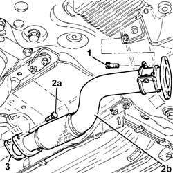
1. Undo the bolt fixing the rigid pipe mounting collar for the exhaust pipe between the catalytic converter and the silencer to the bracket.
2. Loosen the collar (2a) and remove the rigid pipe for the exhaust pipe between the catalytic converter and the silencer (2b).
3. Remove the seal.
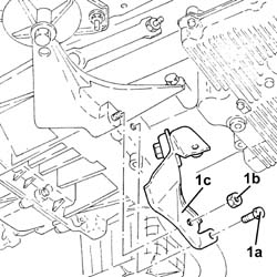
1. Undo the bolt (1a) and the nut (1b) and remove the exhaust pipe mounting (1c).
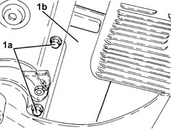
1. Undo the bolts (1a) and remove the heat shield (1b).
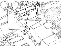
Position a hydraulic jack beneath the engine.
1. Undo the bolt (1a) and the nut (1b) and remove the reinforcement rod (1c).
1. Undo the bolts (1a) and remove the rigid power unit rear support (1b).
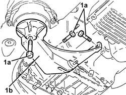
Refitting
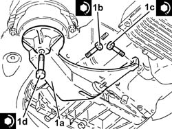
1. Place the power unit rigid rear support (1a) in its housing and secure it tightening the bolts (1b, (1c) and (1d) to the recommended torque.
| Fastening | Component | Ø | Value (daNm) | |
|---|---|---|---|---|
| 1b | Bolt | RIGID REAR SUPPORT POWER UNIT | M12 | (Gearbox side) 7.2 - 8.8 |
| Fastening | Component | Ø | Value (daNm) | |
|---|---|---|---|---|
| 1c | Bolt | RIGID REAR SUPPORT POWER UNIT | M12 | (Engine crankcase side) 6.8 - 8.3 |
| Fastening | Component | Ø | Value (daNm) | |
|---|---|---|---|---|
| 1d |
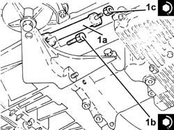
1. Place the reinforcement rod (1a) in its housing and fasten it tightening the bolt (1b) and the nut (1c) to the recommended torque.
| Fastening | Component | Ø | Value (daNm) | |
|---|---|---|---|---|
| 1b | Bolt | REINFORCEMENT ROD FOR POWER UNIT RIGID REAR SUPPORT | M12 |
| Fastening | Component | Ø | Value (daNm) | |
|---|---|---|---|---|
| 1c |
Remove the hydraulic jack from beneath the engine.
Place the heat shield back in its housing and secure it using the bolts.
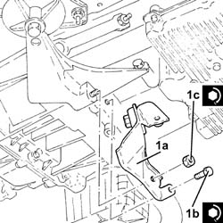
1. Place the exhaust pipe mounting (1a) in its housing and fasten it tightening the bolt (1b) and the nut (1c) to the recommended torque.
| Fastening | Component | Ø | Value (daNm) | |
|---|---|---|---|---|
| 1b | Bolt | EXHAUST PIPE RIGID MOUNT | M8 | 2.3 ÷ 2.8 |
| Fastening | Component | Ø | Value (daNm) | |
|---|---|---|---|---|
| 1c | Nut | EXHAUST PIPE RIGID MOUNT | M8 |
1. Place the rigid pipe for the exhaust pipe between the catalytic converter and the silencer (1a) complete with gasket (1b) back in its housing and secure it to the front exhaust silencer tightening the bolts (1c) to the recommended torque.
| Fastening | Component | Ø | Value (daNm) | |
|---|---|---|---|---|
| 1c | Bolt | RIGID EXHAUST PIPE | M8 |
2. Tighten the bolt fixing the rigid pipe mounting collar for the exhaust pipe between the catalytic converter and the silencer to the bracket.
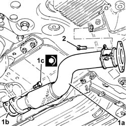
Proceed with the refitting
Op. 1080B62 CATALYTIC CONVERTER - R + R.
Proceed with the refitting
Op. 1076A48 CATALYTIC CONVERTER HEAT SHIELD - R R.
Proceed with the refitting
Op. 1016A40 IGNITION COIL COVER ON CYLINDER HEAD- R+R.
Proceed with the refitting
Op. 5040A26 COMPRESSOR MOUNT - R R.
Proceed with the refitting
Op. 5040A20 AIR CONDITIONER COMPRESSOR - R+R - INCLUDES FLUID LEVEL CHECK AND TOP UP IF NECESSARY.
Proceed with the refitting
Op. 7055B54 UNDER-ENGINE GUARD - R R.
Proceed with the refitting
Op. 4450B04 RIGHT FRONT WHEEL R R.
Refill the air conditioning refrigerant circuit
Op. 0010T84 COOLANT FOR AIR CONDITIONING SYSTEM DEHYDRATE AND RECHARGE.
Connect the negative battery terminal (-).
Remove the vehicle from the lift.
Removing
Position the vehicle on a lift.
Proceed with the removal
Op. 7055B54 UNDER-ENGINE GUARD - R R.
Proceed with the removal
Op. 1076B82 LEFT EXHASUST PIPE BETWEEN CATALYTIC PRECONVERTER AND CONVERTER R R.
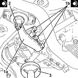
1. Position a hydraulic jack beneath the gearbox.
2. Unscrew the bolt securing the power unit rigid rear support to the flexible mounting.
3. Undo the bolts (3a) and remove the power unit rear support (3b).
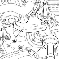
Refitting
1. Place the power unit rigid rear support (1a) in its housing and secure it to the differential tightening the bolts (1b) to the recommended torque.
| Fastening | Component | Ø | Value (daNm) | |
|---|---|---|---|---|
| 1b | Bolt | RIGID REAR SUPPORT POWER UNIT | M16 | (Manual gearbox/differential side) 10.8 - 13.2 |
2. Tighten the bolt securing the power unit side rigid rear support to the flexible mounting to the recommended torque.
| Fastening | Component | Ø | Value (daNm) | |
|---|---|---|---|---|
| 2 |
3. Remove the hydraulic jack from beneath the gearbox
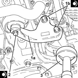
Proceed with the refitting
Op. 1076B82 LEFT EXHASUST PIPE BETWEEN CATALYTIC PRECONVERTER AND CONVERTER R R.
Proceed with the refitting
Op. 7055B54 UNDER-ENGINE GUARD - R R.
Remove the vehicle from the lift.
Removing
Position the vehicle on a lift.
Proceed with the removal
Op. 7055B54 UNDER-ENGINE GUARD - R R.
1. Position a hydraulic jack beneath the gearbox.
2. Undo the nut securing the power unit rigid rear support to the flexible mounting.
3. Undo the bolts (3a) and remove the power unit rear support (3b).
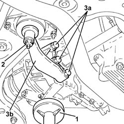
Refitting
1. Place the power unit rigid rear support (1a) in its housing and secure it to the differential tightening the bolts (1b) to the recommended torque.
| Fastening | Component | Ø | Value (daNm) | |
|---|---|---|---|---|
| 1b | Bolt | RIGID REAR SUPPORT POWER UNIT | M12 | (Manual gearbox/differential side) 6.8 - 8.3 |
2. Tighten the nut securing the power unit side rigid rear support to the flexible mounting to the recommended torque.
| Fastening | Component | Ø | Value (daNm) | |
|---|---|---|---|---|
| 2 |
3. Remove the hydraulic jack from beneath the gearbox
Proceed with the refitting
Op. 7055B54 UNDER-ENGINE GUARD - R R.
Remove the vehicle from the lift.
Removing
Position the vehicle on a lift.
Make sure that the ignition key is in the OFF position, then disconnect the negative battery terminal.
| Description | Connector | |
|---|---|---|
| Battery | Vedere A1B BATTERIA ( CABLAGGI ) |
Op. 1072C44 EXHAUST MANIFOLD HEAT SHIELD ON BULKHEAD - R+R
Proceed with the removal
Op. 1080B40 CATALYTIC PRE-CONVERTER - R R.
Position a hydraulic jack beneath the gearbox.
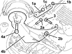
1. Undo the bolt (1a) and the nut (1b) and remove the reinforcement rod (1c).
2. Undo the bolt (2a) and the nut (2b) fastening the power unit rigid rear support to the gearbox.
3. Unscrew the bolt securing the power unit rigid rear support to the crankcase sump.
4. Undo the bolts (4a) and remove the power unit rigid rear support (4b).
Refitting
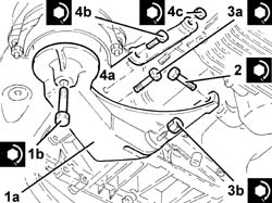
1. Place the power unit rigid rear support (1a) in its housing and secure it to the flexible mounting tightening the bolt (1b) to the recommended torque.
| Fastening | Component | Ø | Value (daNm) | |
|---|---|---|---|---|
| 1b | Bolt | RIGID REAR SUPPORT POWER UNIT | M12 | (Flexible mounting side) 7.5 - 9.2 |
2. Tighten the bolt securing the power unit rigid rear support to the crankcase sump to the recommended torque.
| Fastening | Component | Ø | Value (daNm) | |
|---|---|---|---|---|
| 2 | Bolt | RIGID REAR SUPPORT POWER UNIT | M12 | (Crankcase sump side) 6.8 - 8.3 |
3. Tighten the bolt (3a) and the nut (3b) fastening the power unit rigid rear support to the gearbox to the recommended torque.
| Fastening | Component | Ø | Value (daNm) | |
|---|---|---|---|---|
| 3a | Bolt | RIGID REAR SUPPORT POWER UNIT | M12 | (Gearbox side) 6.8 - 8.3 |
| Fastening | Component | Ø | Value (daNm) | |
|---|---|---|---|---|
| 3b | Nut | RIGID REAR SUPPORT POWER UNIT | M12 | (Gearbox side) 7.2 - 8.8 |
4. Place the reinforcement rod (4a) in its housing and fasten it tightening the bolt (4b) and the nut (4c) to the recommended torque.
| Fastening | Component | Ø | Value (daNm) | |
|---|---|---|---|---|
| 4b | Bolt | REINFORCEMENT ROD FOR POWER UNIT RIGID REAR SUPPORT | M12 | (Power unit rigid rear support side) 6.8 - 8.3 |
| Fastening | Component | Ø | Value (daNm) | |
|---|---|---|---|---|
| 4c | Nut | REINFORCEMENT ROD FOR POWER UNIT RIGID REAR SUPPORT | M8 | (Engine crankcase side) 2.4 |
Remove the hydraulic jack positioned underneath the gearbox
Op. 1080B40 CATALYTIC PRE-CONVERTER - R R
Proceed with the refitting
Op. 1072C44 EXHAUST MANIFOLD HEAT SHIELD ON BULKHEAD - R+R.
Connect the negative battery terminal (-).
Remove the vehicle from the lift.
Parts & tools for this job Staging For 2003 Alfa Romeo GT
- PARTEngine gasket setSearch: Alfa Romeo GT 2003 engine gasket set
- TOOLTorque wrenchSearch: 3/8 inch torque wrench
- TOOLFeeler gauge setSearch: feeler gauge set
Links open Amazon search results in a new tab. As an Amazon Associate I earn from qualifying purchases.