
Ball joint - upper
- Make
- Land Rover
- Model
- Range Rover L322 Range Rover Service Procedures
- Section
- REPAIRS › Ball joint - upper
REAR SUSPENSION
REPAIRS
64-5
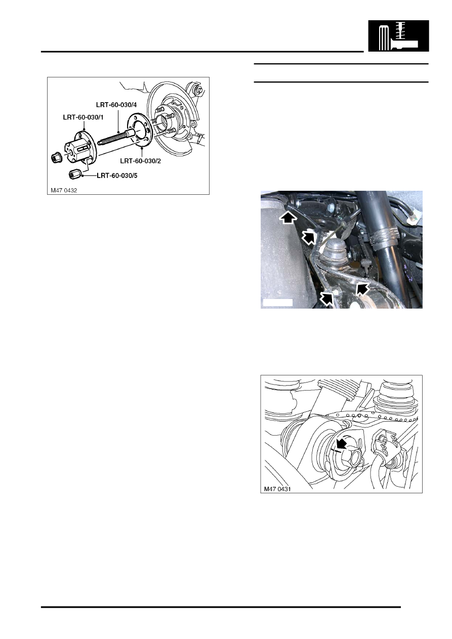
7. Fit LRT-60-030/4 to drive shaft.
8. Fit LRT-60-030/1 with spacer LRT-60-030/2
and secure with nuts LRT-60-030/5.
9. Fit nut to LRT-60-030/4 and tighten nut to pull
drive shaft into drive flange.
10. Remove tools.
11. Locate handbrake cable to backplate, fit bolt
and tighten to 8 Nm (6 lbf.ft).
12. Position handbrake cable bracket to upper arm,
fit Allen screw and tighten to 5 Nm (3.7 lbf.ft).
13. Clean ABS sensor, smear sensor with an anti-
seize grease and fit sensor to hub.
LUBRICANTS AND SEALANTS,
Lubrication.
14. Fit Allen screw securing ABS sensor and
tighten to 8 Nm (6 lbf.ft).
15. Fit tie rod.
16. Clean backplate and brake disc with brake
cleaning fluid.
17. Clean expander.
18. Fit expander.
19. Position brake shoe assembly, fit retainers and
upper return spring.
20. Fit brake disc.
21. Fit new hub nut and tighten to 420 Nm (311
lbf.ft).
22. Stake nut to shaft.
23. Adjust handbrake.
24. Fit road wheel and tighten nuts to 140 Nm (103
lbf.ft).
25. Remove stands and lower vehicle.
26. Check wheel alignment.
27. Tighten bolt securing upper arm to hub to 165
Nm (121 lbf.ft).
Ball joint - upper
$% 64.15.07
Remove
1. Raise rear of vehicle and support under body.
WARNING: Do not work on or under a
vehicle supported only by a jack. Always
support the vehicle on safety stands.
2. Remove road wheel.
3. Release ABS sensor lead from upper arm.
4. Remove Allen screw securing brake pipe.
5. Position jack under damper mounting bracket
to support lower arm.
6. Reference mark eccentric in relationship to
upper arm.
7. Remove and discard nut and bolt securing hub
to upper arm. Release hub from arm.
M64 0199
Parts & tools for this job Staging For Land Rover Range Rover
- TOOLTie rod end toolSearch: tie rod end puller
- TOOLBall joint separatorSearch: ball joint separator
- FLUIDPower steering fluidSearch: Land Rover power steering fluid
Links open Amazon search results in a new tab. As an Amazon Associate I earn from qualifying purchases.