
Link - anti roll bar
- Make
- Land Rover
- Model
- Range Rover L322 Range Rover Service Procedures
- Section
- REPAIRS › Link - anti roll bar
FRONT SUSPENSION
60-4
REPAIRS
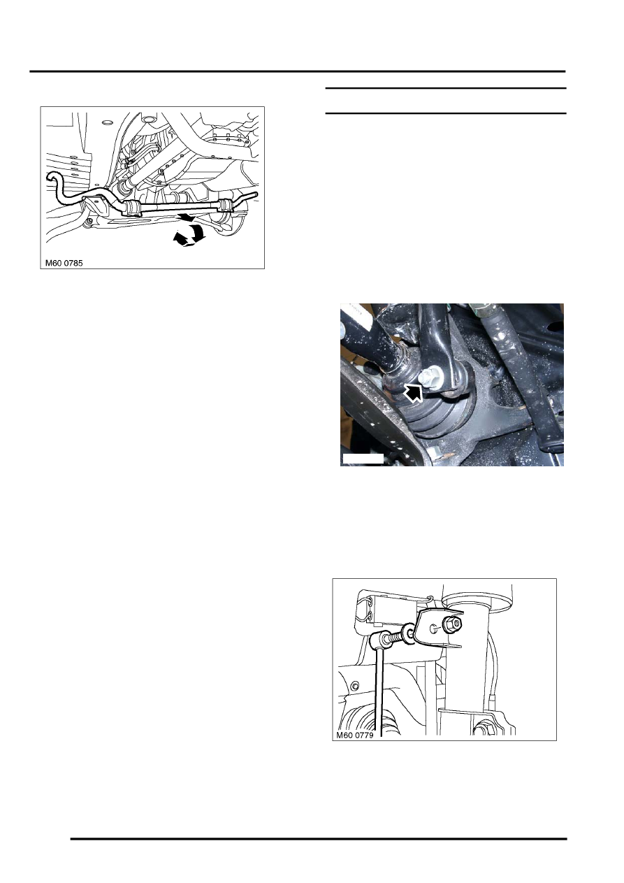
11. Manoeuvre anti-roll bar over subframe and
remove from vehicle.
CAUTION: The anti roll bar clamps are
supplied with the anti roll bar and must not
be removed.
Refit
1. Position anti-roll bar to subframe and
manoeuvre into position.
2. Locate clamps and lightly tighten nuts.
3. Raise subframe, fit new bolts securing
subframe to body and tighten to 165 Nm (122
lbf.ft). Tighten 2 rear bolts a further 90
°
.
4. Tighten bolts securing subframe to front
crossmember to 132.5 Nm (97 lbf.ft).
5. Connect anti-roll bar links, fit nuts and tighten to
100 Nm (74 lbf.ft).
6. Fit front road wheels and tighten nuts to 140
Nm (103 lbf.ft).
7. Remove supports and lower vehicle.
8. Fit undertray.
9. Tighten anti-roll bar bush clamp nuts to 19 Nm
(14 lbf.ft).
10. Fit anti-roll bar heatshields and tighten fixings.
11. Check wheel alignment.
wheel alignment - check & adjust.
Link - anti roll bar
$% 60.10.02
Road wheels must be in straight ahead position
during this operation
Remove
1. Raise front of vehicle.
WARNING: Do not work on or under a
vehicle supported only by a jack. Always
support the vehicle on safety stands.
2. Remove road wheel.
3. Remove nut securing anti-roll bar link to anti-
roll bar.
CAUTION: Use an open ended spanner on
flats provided to prevent ball joint rotating.
4. Release link from anti-roll bar.
5. Remove nut securing anti-roll bar link to
damper.
M60 0778
Parts & tools for this job Staging For Land Rover Range Rover
- TOOLCoil spring compressorSearch: coil spring compressor
- TOOLBall joint separatorSearch: ball joint separator
- PARTFront shock absorbersSearch: Land Rover Range Rover front shock absorbers
Links open Amazon search results in a new tab. As an Amazon Associate I earn from qualifying purchases.