Workshop Manuals Factory service & repair Land Rover
01 Range Rover 2002MY ON Workshop Manual - Service Procedures - LM - 6th Edition - NAS02 03 04 05 06 07 08 09 10 11 12 13 14 15 16 17 18 19 20 21 22 23 24 25 INTRODUCTION26 27 28 GENERAL INFORMATION29 30 31 GENERAL DATA32 33 IDENTIFICATION NUMBERS34 35 TORQUE WRENCH SETTINGS36 37 LIFTING AND TOWING38 39 CAPACITIES, FLUIDS, LUBRICANTS AND SEALANTS40 MAINTENANCE41 42 ENGINE - V843 44 45 46 EMISSION CONTROL - V847 ENGINE MANAGEMENT SYSTEM - V848 49 FUEL DELIVERY SYSTEM - V850 51 COOLING SYSTEM - V852 53 54 55 MANIFOLD AND EXHAUST SYSTEM - V856 57 58 TRANSFER BOX59 60 61 AUTOMATIC TRANSMISSION - ZF 5HP2462 63 DRIVESHAFTS64 65 FINAL DRIVE66 67 68 FRONT DIFFERENTIAL69 70 71 72 STEERING73 FRONT SUSPENSION74 75 REAR SUSPENSION76 77 BRAKES78 RESTRAINT SYSTEMS79 80 81 82 DOORS83 EXTERIOR FITTINGS84 85 INTERIOR FITTINGS86 87 88 SCREENS89 90 91 SEATS92 93 94 SUNROOF95 BODY DIMENSIONS96 97 98 99 PANEL REPAIRS100 101 102 103 BODY SEALING MATERIALS104 105 106 107 CORROSION PREVENTION AND SEALING108 109 PAINTING110 111 HEATING AND VENTILATION112 AIR CONDITIONING113 114 115 WIPERS AND WASHERS116 CHARGING AND STARTING117 118 119 LIGHTING120 CONTROL UNITS AND RELAYS121 122 DRIVING AIDS123 124 ALARM SYSTEM AND HORN125 126 WINDOWS127 128 NAVIGATION AND IN CAR ENTERTAINMENT129 HARNESSES130 131 INSTRUMENTS
Land Rover L322 Range Rover Service Procedures68 · FRONT DIFFERENTIAL
68 · General

Differential assembly - Td6

Make
Land Rover
Model
Range Rover L322 Range Rover Service Procedures
Section
REPAIRS › Differential assembly - Td6
FRONT DIFFERENTIALDifferential assembly - Td6 · page 1 of 3
background image

FRONT DIFFERENTIAL

REPAIRS

54-3

REPAIRS

Differential assembly - Td6 

$% 54.10.01

Remove

1. Position vehicle on lift.
2. Disconnect battery earth lead.
3. Remove cooling fan.


 + 

 COOLING SYSTEM - Td6, REPAIR, 

Coupling unit - viscous fan.

4. Remove air intake plenum.


 + 

 HEATING AND VENTILATION, 

REPAIRS, Filter - fresh air intake.

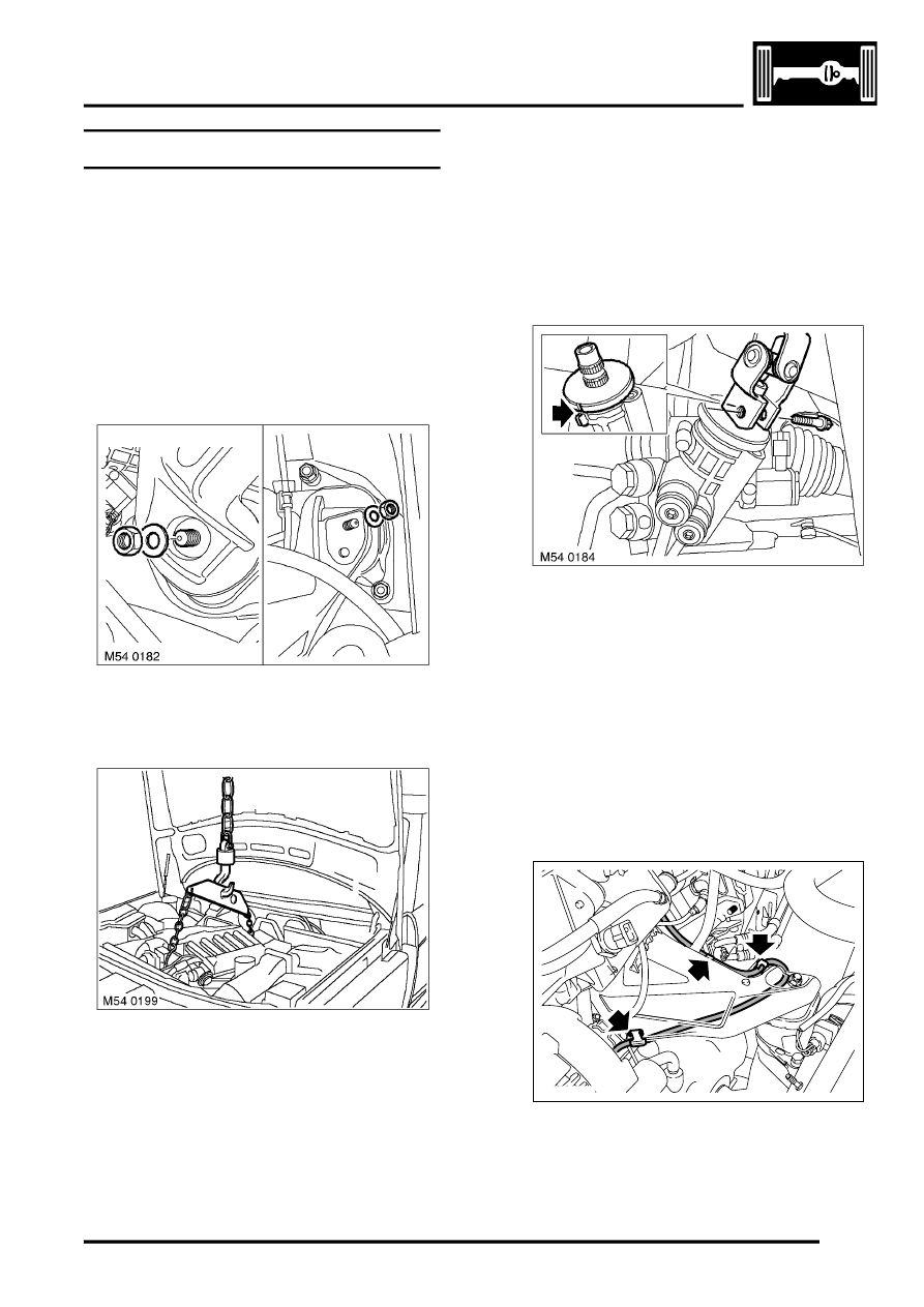
5. Remove 2 nuts securing engine brackets to 

mountings.

6. Fit LRT-12-216 to engine lifting eyes.
7. Connect chain to lifting bracket and take weight 

of engine.

8. Drain oil from differential.


 + 

 FRONT DIFFERENTIAL, 

ADJUSTMENTS, Front differential - drain 
and refill.

9. Remove front propeller shaft.


 + 

 DRIVESHAFTS, REPAIRS, Propeller 

shaft - front.

10. Remove RH drive shaft seal.


 + 

 DRIVESHAFTS, REPAIRS, Seal - 

drive shaft - front - RH.

11. Remove differential oil seal.


 + 

 FRONT DIFFERENTIAL, REPAIRS, 

Oil seal - differential housing.

12. Remove Torx screw from steering column 

lower clamp.

13. Rotate steering wheel to straight ahead 

position, align pinion timing marks and remove 
ignition key.

CAUTION: Do not turn the steering wheel 
with the intermediate shaft or universal joint 
disconnected as damage to the rotary 
coupler and the steering wheel switches 
may occur.

14. Disconnect column from pinion.

15. Release vacuum hose from 3 clips on engine 

LH mounting bracket.

M12 7525

Parts & tools for this job Staging For Land Rover Range Rover

Links open Amazon search results in a new tab. As an Amazon Associate I earn from qualifying purchases.