
Differential assembly (page 3 of 3)
- Make
- Land Rover
- Model
- Range Rover L322 Range Rover Service Procedures
- Section
- REPAIRS
FINAL DRIVE
REPAIRS
51-5
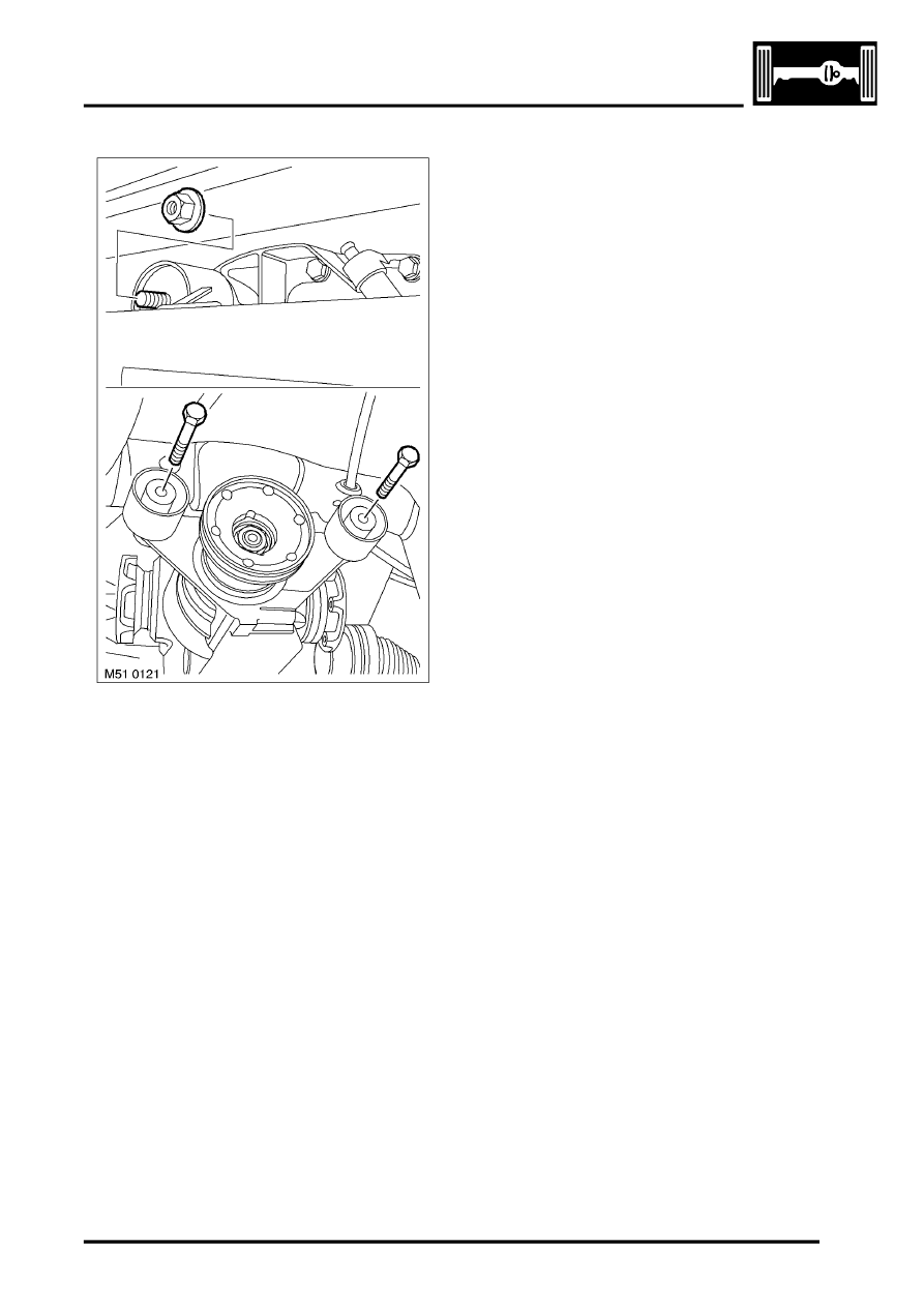
20. Remove and discard 2 bolts and 1 nut and bolt
securing differential to the subframe. Remove
differential assembly.
Refit
1. Position jack and raise differential into position.
2. Fit new bolts securing differential to subframe
and tighten front 2 bolts to 100 Nm (74 lbf.ft)
and new rear nut and bolt to 165 Nm (121 lbf.ft).
3. Clean end of drive shaft and location in
differential.
4. Locate drive shaft to differential.
5. Clean lower arm and hub mating faces.
6. Align hub to lower arm, fit and lightly tighten nut
and bolt.
7. Clean bolt plates, position plates, fit new bolts
securing drive shaft to differential drive flange
and tighten to 40 Nm (30 lbf.ft) plus a further
60
°
8. Repeat procedure for other side.
9. Connect breather hose to differential.
10. Fit road wheel and tighten nuts to 140 Nm (103
lbf.ft).
11. Remove stands and lower vehicle.
12. Tighten bolts securing lower arms to hubs to
250 Nm (184 lbf.ft).
13. Clean differential and propeller shaft flange
mating faces.
14. Remove nuts securing support bearing,
connect propeller shaft to differential flange and
locate support bearing. Fit nuts securing
support bearing but do not tighten at this stage.
15. Fit nuts securing propeller shaft to differential
flange and tighten to 70 Nm (52 lbf.ft).
16. Tighten nuts securing propeller shaft support
bearing to 21 Nm (15 lbf.ft).
17. Fit fuel tank heat shield and secure with screws.
18. Fit centre heat shield and secure with nuts.
19. Fill differential to correct level with oil.
FINAL DRIVE, ADJUSTMENTS, Rear
differential - drain and refill.
20. Fit exhaust system.
Parts & tools for this job Staging For Land Rover Range Rover
- TOOLTorque wrenchSearch: 3/8 inch torque wrench
- TOOLSocket setSearch: socket set metric
- BOOKHaynes manualSearch: Haynes manual Land Rover Range Rover
Links open Amazon search results in a new tab. As an Amazon Associate I earn from qualifying purchases.