
Front suspension FRAME - R.R.
- Make
- Lancia
- Model
- Thesis Factory Service Manual
- Year
- 2002–2009
- Section
- Front suspension › Front suspension FRAME - R.R.
Front suspension FRAME - R.R.
Removing
- Working from inside the vehicle, follow the instructions below making sure that the wheels are perfectly straight and that the ignition key is not inserted:
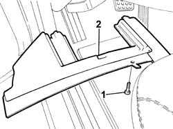
1. Undo the bolts fixing the trim under the dashboard, driver's side.
2. Remove the trim under the dashboard, driver's side.
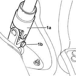
1. Release the steering column universal joint (1a) undoing the fixing bolt (1b).
- Position the vehicle on a lift.
- Open the boot, remove the cover on the left hand side and disconnect the negative battery lead.
See in Op. 7040D50 ENGINE COMPARTMENT UPPER SOUND INSULATION SHIELD - R.R.
See in Op. 4450B04 Right FRONT WHEEL (one) - R.R.
See in Op. 4450B02 Left FRONT WHEEL (one) - R.R.
- Raise the vehicle on the lift.
See in Op. 7055B54 PROTECTION/GUARD under engine - R.R.
See in Op. 7055B64 Engine compartment DUST SEAL in front wheel arch (one), left or right - R.R.
- Left side.
See in Op. 7055B42 FRONT WHEEL ARCH LINER (one), left or right - R.R.
- Left side.
- Position a suitable container for collecting the engine coolant.
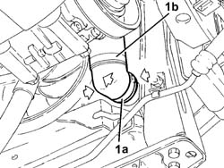
1. Open the rapid attachment band (1a) and disconnect the lower pipe (1b) from the radiator (1c).
- Position a suitable container for collecting the power assisted steering fluid
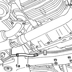
1. Open the retaining band (1a) and disconnect the flexible return pipe (1b) to the power assisted steering fluid reservoir from the duplex pipes, then leave the system to drain.
- Lower the lift.
- [5050A12]
See in Op. 1088B10 Engine coolant SUPPLY RESERVOIR - R.R.
See in Op. 1008C10 Power unit REACTION ROD - Replace
See in Op. 1048A21 AIR INLET HOSE FROM INTAKE TO FILTER - R.R.
See in Op. 1048A28 vacuum air circuit resonator pipe - r+r
See in Op. 1016A42 LEFT CYLINDER HEAD IGNITION COIL COVER - R.R.
See in Op. 1048A11 COMPLETE AIR FILTER -R.R.
See in Op. 1088E10 Radiator cooling FAN - R.R.
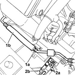
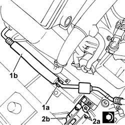
1. Release the air conditioning system pipe (1b) from the retaining spring (1a) on the frame.
2. Undo the nuts (2a) fixing the coolant radiator mounting plates (2a) on the frame.
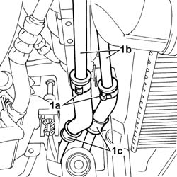
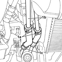
1. Open the bands (1a) retaining the power assisted steering pipes (1b) to the heat exchanger (1c) and disconnect them.
See in Op. 5050B32 Front windscreen WIPER ARM/S - R.R.
See in Op. 7055A18 Winsdcreen base TRIM - R.R.
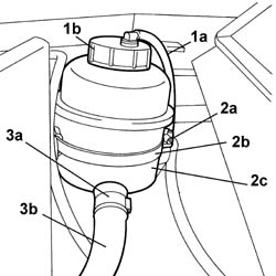
1. Disconnect the breather pipe (1a) from the reservoir cap (1b).
2. Undo the bolt (2a) fixing the power assisted steering fluid reservoir (2c) retaining band (2b).
3. Open the reservoir pipe (3b) retaining bands (3a), then disconnect the actual pipes, releasing them from the engine compartment bulkhead.
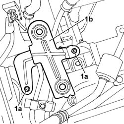
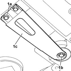
1. Undo the two fixing nuts (1a) and remove the air filter casing mounting bracket (1b).
- Working on the gearbox side, release the left suspension as described below:
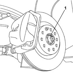
1. Remove the staking from the nut fixing the gearbox side wheel hub and undo it.
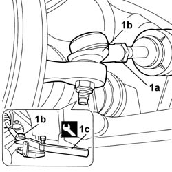
1. Undo the nut (1a) fixing the steering box track rod end (1b) and disconnect it using the extractor (1c).
| Description | Code | Function | |
|---|---|---|---|
| 1c | Head extractor | 1.847.035.000 | Extracting steering rod pin from stub axle |
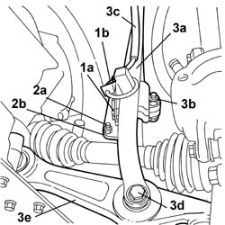
1. Undo the bolt (1a) fixing the vibration sensor bracket (1b) and move it aside.
2. Undo the nut (2a) fixing the anti-roll bar connecting rod (2b).
3. Undo the upper bolt (3a) fixing the selector fork (3b) to the shock absorber (3c) and the lower bolt (3d) fixing it to the front suspension arm (3e), then remove the selector fork.
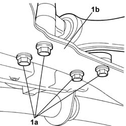
1. Undo the fastenings (1a) securing the front track control arm (1b) to the frame.
1. Undo the fastening (1a) securing the lower rear track control arm (1b) to the frame.
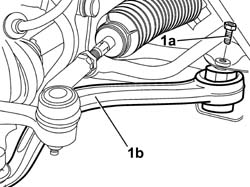
1. Release the front suspension arm (1a) and the rear suspension arm (1b) from the frame, keeping the thrust washers.
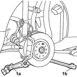
1. Release the wheel hub (1a) from the left driveshaft (1b) leaving the latter secured to the gearbox.
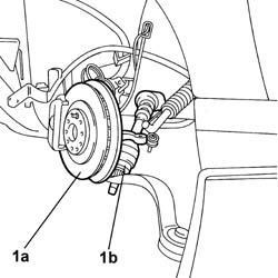
- Proceed in the same way on the engine side to release the right suspension.
1. Disconnect the electrical connection (1a) for the headlamp alignment adjustment sensor (1b).
| Description | Connector | |
|---|---|---|
| 1a | Headlamp alignment corrector front potentiometer (CAF) | K001 |
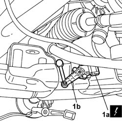
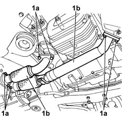
1. Undo the nuts (1a) fixing the flanges for the pipes (1b) between the pre-catalyzers and the catalyzer and remove the actual pipes complete with the gaskets underneath.
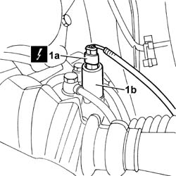
1. Working on the gearbox side, disconnect the electrical connection (1a) for the servotronic actuator (1b) located on the steering box.
| Description | Connector | |
|---|---|---|
| 1a | Servotronik solenoid valve | L070 |
See in Op. 5505A38 BODYSHELL POWER UNIT EARTH LEAD - R.R.
- Secure the engine coolant radiator to the bodyshell, as appropriate.
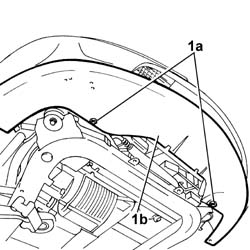
1. With the vehicle raised, undo the bolts (1a) fixing the bumper (1b) to the radiator mounting brackets, then remove the actual brackets.
- Position a container for collecting the power assisted steering fluid
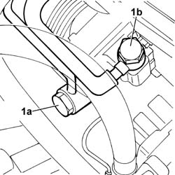
1. Undo the connectors on the power assisted steering pump for the fluid return (1a) and supply (1b) pipes, keeping the copper washers underneath.
1. Open the retaining clip (1a) on the timing belt protective covers and release the power assisted steering pipes (1b).
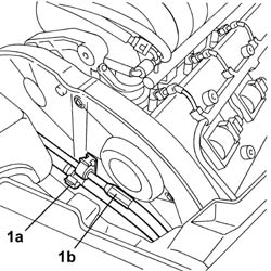
1. Release the retaining band for the cable loom on the left suspension turret and place the wiring to the side to allow the subsequent fitting of the power unit supporting crossmember.
1. Secure a suitable bracket (1b) for supporting the power unit using the hook (1c) to the bracket (1a) on the engine for the rod (1d).
2. Fit the tool (2a), complete with support mountings (2b), in the area in front of the suspension turret.
| Description | Code | Function | |
|---|---|---|---|
| 2a | Crossmember | 1.870.595.000 | Power unit support |
| Description | Code | Function | |
|---|---|---|---|
| 2b | Support mountings | 1.870.650.000 | Power unit support |
3. Fit the tools (3a) and (3b), then drill the latter to allow the positioning of the bracket (3c) and the bolt retaining it to the lower crossmember.
| Description | Code | Function | |
|---|---|---|---|
| 3a | Crossmember | 1.860.851.003 | Power unit support |
| Description | Code | Function | |
|---|---|---|---|
| 3b | Vertical support | 1.870.748.000 | Power unit support |
- Acting on the rod, tension the lifting system.
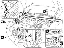
- Raise the lift
1. Undo the fixing bolts (1a) and remove the heat shield (1b).
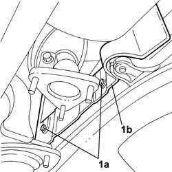
1. Open the retaining clip (1a) for the supply pipe (1b) from the pump to the steering box on the casing.
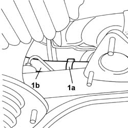
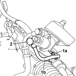
1. Undo the bolt (1a) fixing the supply pipe to the steering box (1b).
2. Undo the connector and disconnect the supply pipe to the steering box, keeping the gaskets that are underneath.
Secure the pipe to the bodyshell, as best as possible, in order to prevent power assisted steering fluid leaks and to facilitate the subsequent operation of removing the frame.
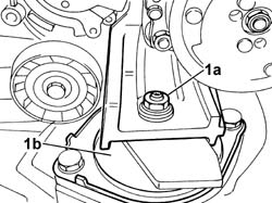
1. Undo the bolt (1a) fixing the timing side engine support (1b).
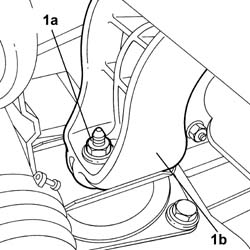
1. Undo the nut (1a) fixing the centre rear engine support (1b).
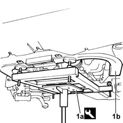
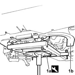
1. Position the tool for supporting the power unit-chassis assembly (1a), complete with hydraulic jack, under the housings in the engine support frame (1b).
| Description | Code | Function | |
|---|---|---|---|
| 1a | Power unit support frame | 1.870.835.000 | Removing-refitting power unit |
1. Undo the two rear bolts (1a) and the front bolt (1b) fixing each of the two rear engine mounting brackets (1c).
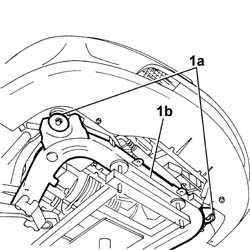
1. Undo the two front bolts (1a) fixing the frame (1b) to the bodyshell.
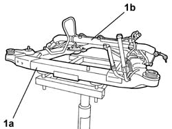
1. Completely lower the jack and release the front suspension frame (1a), complete with steering box (1b) and pipes with the exception of the supply pipe from the pump to the steering box.
Refitting
- Position the front suspension frame, complete with steering box and pipes, and raise the jack.
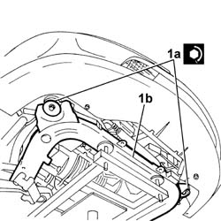
1. Tighten the two front bolts (1a) fixing the frame (1b) to the bodyshell to the recommended torque.
| Value - daNm | Fastening | Component | Ø | |
|---|---|---|---|---|
| 1a | 13 | Bolt | FRONT SUSPENSION SUBFRAME | M12 X 1.25 |
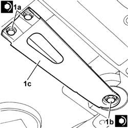
1. Tighten the two rear bolts (1a) and the front bolt (1b) fixing each of the two rear engine mounting brackets (1c).
| Value - daNm | Fastening | Component | Ø | |
|---|---|---|---|---|
| 1a | 5 | Bolt | FRONT SUSPENSION SUBFRAME | M10 X 1.25 |
| Value - daNm | Fastening | Component | Ø | |
|---|---|---|---|---|
| 1b | 13 | Bolt | FRONT SUSPENSION SUBFRAME | M12 X 1.25 |
- Remove the tool supporting the power unit - chassis assembly
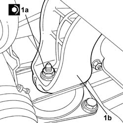
1. Tighten the nut (1a) fixing the centre rear engine support (1b) to the recommended torque.
| Value - daNm | Fastening | Component | Ø | |
|---|---|---|---|---|
| 1a | (to the flexible mounting) 4 | Nut | RIGID REAR SUPPORT POWER UNIT | M10 |
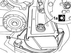
1. Tighten the nut (1a) fixing the timing side engine support (1b) to the recommended torque.
| Value - daNm | Fastening | Component | Ø | |
|---|---|---|---|---|
| 1a | (Engine support) 4.5 | Nut | RIGID ENGINE MOUNT, TIMING SIDE | M10 X 1.25 |
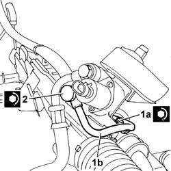
1. Tighten the bolt (1a) fixing the rigid section of the supply pipe (1b) to the steering box to the recommended torque.
2. Tighten the connector for the supply pipe to the power assisted steering box to the recommended torque.
| Value - daNm | Fastening | Component | Ø | |
|---|---|---|---|---|
| 1a | 0.5 | Bolt | PIPE BTWN PUMP + POWER STEERING BOX | M6 |
| Value - daNm | Fastening | Component | Ø | |
|---|---|---|---|---|
| 2 | 4 | Connector | PIPE BTWN PUMP + POWER STEERING BOX | M14 x1.5 |
- Close the retaining clip for the supply pipe from the pump to the steering box on the casing.
- Position the heat shield and tighten the fixing bolts.
- Lower the lift.
- Remove the power unit support system.
- Position the cable loom on the left suspension turret and secure the retaining band.
- Secure the power assisted steering pipes to the timing belt covers closing the retaining band.
1. Connect the connectors for the pump return (1a) and supply (1b) pipes, positioning the copper washers, then tighten them to the recommended torque.
| Value - daNm | Fastening | Component | Ø | |
|---|---|---|---|---|
| 1a | 4 | Connector | POWER STEERING PUMP SUPPLY PIPE | M18 X 1.5 |
| Value - daNm | Fastening | Component | Ø | |
|---|---|---|---|---|
| 1b | 4 | Connector | POWER ASSISTED STEERING PUMP/BOX PIPE | M16 X 1.5 |
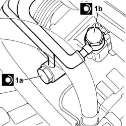
- With the vehicle raised, position the radiator mounting brackets, then tighten the bolts fixing the bumper to the mounting brackets.
- Position the radiator on the mounting brackets.
See in Op. 5505A38 BODYSHELL POWER UNIT EARTH LEAD - R.R.
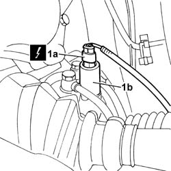
1. Working on the gearbox side, connect the electrical connection for the servotronic actuator located on the steering box.
| Description | Connector | |
|---|---|---|
| 1a | Servotronik solenoid valve | L070 |
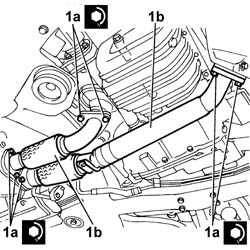
1. Position the pipes between the pre-catalyzers and the catalyzer, complete with seals, then tighten the nuts (1a) fixing the pipe flanges (1b) to the recommended torque.
| Value - daNm | Fastening | Component | Ø | |
|---|---|---|---|---|
| 1a | 2.8 | Nut | EXHAUST PIPE MOUNTS/FASTENERS | M8 |
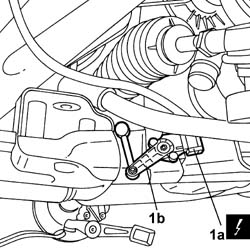
1. Connect the electrical connection (1a) for the headlamp alignment adjustment sensor (1b).
| Description | Connector | |
|---|---|---|
| 1a | Headlamp alignment corrector front potentiometer (CAF) | K001 |
- Fit the wheel hub on the left driveshaft.
- Positioning the thrust washers, fit the front and rear suspension arms in the housings in the frame.
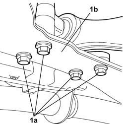
1. Tighten the bolt (1a) fixing the lower rear track control arm (1b) to the frame to the recommended torque.
| Value - daNm | Fastening | Component | Ø | |
|---|---|---|---|---|
| 1a | 10 | Bolt | LOWER FRONT TRACK CONTROL ARMS | M12 x1.25 |
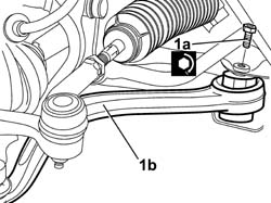
1. Tighten the bolts (1a) fixing the lower front track control arm (1b) to the frame to the recommended torque.
| Value - daNm | Fastening | Component | Ø | |
|---|---|---|---|---|
| 1a | 7.4 | Bolt | LOWER FRONT TRACK CONTROL ARMS | M10x.1.25 |
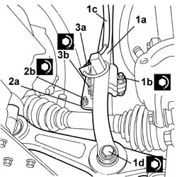
1. Position the selector fork (1a), then tighten the uppwer bolt (1b) fixing the fork to the shock absorber (1c) and the lower bolt (1d) fixing it to the front suspension arm (1e) to the recommended torque.
| Value - daNm | Fastening | Component | Ø | |
|---|---|---|---|---|
| 1b | 11.6 | Bolt | FRONT DAMPER FORK ON WISHBONE | M12 X 1.25 |
| Value - daNm | Fastening | Component | Ø | |
|---|---|---|---|---|
| 1d | 9 | Bolt | LOWER FRONT TRACK CONTROL ARMS | M12 X 1.25 |
2. Secure the anti-roll bar connecting rod (2a) and tighten the fixing nut (2b).
| Value - daNm | Fastening | Component | Ø | |
|---|---|---|---|---|
| 2b | 5,5 | Nut | FRONT ANTI-ROLL BAR | M10 X 1.25 |
3. Position the vibration sensor bracket (3a) and tighten the fixing bolt (3b).
| Value - daNm | Fastening | Component | Ø | |
|---|---|---|---|---|
| 3b | 0.4 | Bolt | JOLTING SENSOR | M5 |
- Connect the steering track rod end to the steering knuckle and tighten the fixing nut to torque.
| Value - daNm | Fastening | Component | Ø | |
|---|---|---|---|---|
| 4.5 | Nut | ADJUSTABLE LINK BALL JOINTS | M10 x 1.25 |
- Tighten the nut securing the driveshaft to the wheel hub to the recommended torque using the angular tightening tool (1b), then stake the nut.
| Value - daNm | Fastening | Component | Ø | |
|---|---|---|---|---|
| 7 | Nut | FRONT HUBS COMPLETE WITH BEARING | M24 |
| Description | Code | Function | |
|---|---|---|---|
| 1b | Torque wrench | 1.820.622.000 |
- Proceed in the same way for the engine side suspension.
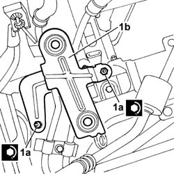
1. Position the air filter casing mounting bracket (1b), then tighten the two fixing nuts (1a) to the recommended torque.
| Value - daNm | Fastening | Component | Ø | |
|---|---|---|---|---|
| 1a | 0.5 | Nut | AIR CLEANER CASE MOUNT | M6 |
- Connect the power assisted steering pipes to the reservoir, then tighten the band retaining the reservoir to the bodyshell.
See in Op. 7055A18 Winsdcreen base TRIM - R.R.
See in Op. 5050B32 Front windscreen WIPER ARM/S - R.R.
1. Connect the power assisted steering pipes (1b) to the heat exchanger (1c), then close the retaining bands (1a).
1. Secure the air conditioning system pipe (1b) to the retaining spring (1a) on the frame.
2. Tighten the nuts (2a) fixing the coolant radiator mounting plates (2a) on the frame to the recommended torque.
| Value - daNm | Fastening | Component | Ø | |
|---|---|---|---|---|
| 2a | 0.5 | Nut | COOLANT RADIATOR SUPPORT BEAM | M6 |
See in Op. 1088E10 Radiator cooling FAN - R.R.
See in Op. 1048A11 COMPLETE AIR FILTER -R.R.
See in Op. 1048A23 Cold AIR INTAKE for air filter - R.R.
See in Op. 1016A42 LEFT CYLINDER HEAD IGNITION COIL COVER - R.R.
See in Op. 1048A28 vacuum air circuit resonator pipe - r+r
See in Op. 1048A21 AIR INLET HOSE FROM INTAKE TO FILTER - R.R.
See in Op. 1008C10 Power unit REACTION ROD - Replace
See in Op. 1088B10 Engine coolant SUPPLY RESERVOIR - R.R.
- [5050A12]
- Connect the flexible return pipe to the power assisted sterring fluid reservoir from the duplex pipes and tighten the retaining band.
See in Op. 7055B42 FRONT WHEEL ARCH LINER (one), left or right - R.R.
- Left side
See in Op. 7055B64 Engine compartment DUST SEAL in front wheel arch (one), left or right - R.R.
- Left side
See in Op. 7055B54 PROTECTION/GUARD under engine - R.R.
- Lower the vehicle
See in Op. 4450B02 Left FRONT WHEEL (one) - R.R.
See in Op. 4450B04 Right FRONT WHEEL (one) - R.R.
- Connect the negative battery lead, then close the boot.
- Tighten the bolt fixing the steering column to the steering box to the recommended torque.
| Value - daNm | Fastening | Component | Ø | |
|---|---|---|---|---|
| 2 | Bolt | STEERING SHAFT MOUNTING | M8 |
- Remove the vehicle from the lift.
See in Op. 0010T70 POWER ASSISTED STEERING FLUID - Replace
See in Op. 0010T21 ENGINE COOLANT - Check density and top up if necessary
See in Op. 7040D50 ENGINE COMPARTMENT UPPER SOUND INSULATION SHIELD - R.R.
Removing
- Position the vehicle on a lift.
- Open the boot, remove the cover on the left hand side and disconnect the negative battery lead.
See in Op. 7040D50 ENGINE COMPARTMENT UPPER SOUND INSULATION SHIELD - R.R.
See in Op. 4450B12 Front WHEELS (two) - R.R.
See in Op. 7055B42 FRONT WHEEL ARCH LINER (one), left or right - R.R.
- (both sides).
See in Op. 7055B64 Engine compartment DUST SEAL in front wheel arch (one), left or right - R.R.
- (both sides).
See in Op. 7055B54 PROTECTION/GUARD under engine - R.R.
See in Op. 7210E10 FRONT BUMPER
See in Op. 1016A40 Ignition COIL COVER on cylinder head - R.R.
See in Op. 1048A28 vacuum air circuit resonator pipe - r+r
See in Op. 1048A21 AIR INLET HOSE FROM INTAKE TO FILTER - R.R.
See in Op. 1048A10 COMPLETE AIR FILTER -R.R.
See in Op. 1088B10 Engine coolant SUPPLY RESERVOIR - R.R.
See in Op. 1008C10 Power unit REACTION ROD - Replace
See in Op. 1016A10 SOUND-PROOFING COVER - R.R.
See in Op. 1048A28 vacuum air circuit resonator pipe - r+r
See in Op. 1048A21 Cold AIR INTAKE PIPE for air filter - R.R.
See in Op. 1048A10 AIR FILTER CASING - R.R.
See in Op. 1088B10 Engine coolant SUPPLY RESERVOIR - R.R.
See in Op. 1008C10 Power unit REACTION ROD - Replace
See in Op. 1016A40 Ignition COIL COVER on cylinder head - R.R.
See in Op. 1048A21 AIR INLET HOSE FROM INTAKE TO FILTER - R.R.
See in Op. 1048A50 air inlet pipe to turbocharger - r + r
See in Op. 1048A10 COMPLETE AIR FILTER -R.R.
See in Op. 1088E10 Radiator cooling FAN - R.R.
See in Op. 1048B14 air delivery pipe between turbo charger and heat exchanger - replace
See in Op. 1088B10 Engine coolant SUPPLY RESERVOIR - R.R.
See in Op. 1008C10 Power unit REACTION ROD - Replace
See in Op. 1016A10 SOUND-PROOFING COVER - R.R.
See in Op. 1048B44 RIGID air supply PIPE from heat exchanger to intake manifold - R.R.
See in Op. 1048A56 UPPER RESONATOR - R.R.
See in Op. 1048A50 air inlet pipe to turbocharger - r + r
See in Op. 1048A21 AIR INLET HOSE FROM INTAKE TO FILTER - R.R.
See in Op. 1048A10 COMPLETE AIR FILTER -R.R.
See in Op. 1088B10 Engine coolant SUPPLY RESERVOIR - R.R.
See in Op. 1008C10 Power unit REACTION ROD - Replace
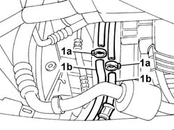
1. Remove the bands (1a) and disconnect the power assisted steering system pipes (1b) from the cooling coil.
Collect the power assisted steering fluid that comes out in a suitable container.
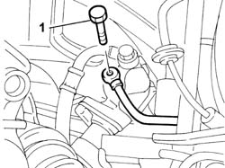
1. Undo the connector on the steering box for the pressurized fluid supply pipe from the pump.
- Release the power assisted steering system pipes from the retaining bands.
See in Op. 1076B68 EXHAUST PIPE FLEXIBLE SECTION - R.R.
See in Op. 1076B50 Exhaust PIPE attachment to engine/manifold - R.R.
See in Op. 1072C44 Exhaust manifold heat shield on BULKHEAD - R.R.
See in Op. 1080B40 CATALYTIC PRECONVERTER - R.R.
See in Op. 1076B70 EXHAUST PIPE BETWEEN PRECATALYZER AND CATALYZER - R.R.
1. Disconnect the band connector the flexible section of the return pipe to the power assisted steering fluid reservoir to the rigid section.
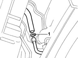
- Secure the radiator-condenser-fan assembly to the upper crossmember.
1. Release the retaining band for the cable loom on the left suspension turret and place the wiring to the side to allow the subsequent fitting of the power unit supporting crossmember.
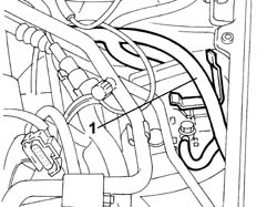
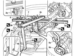
1. Fit a suitable bracket on the cylinder head for supporting the power unit.
2. Fit a suitable hook (2a) on one side of the power assisted steering pump mounting bracket for support and a drilled plate (2b) on the other side, then fasten the two components using a large bolt.
Take care not to damage the rubber support mounting for the power assisted steering pump.
3. Fit the tool (3a), complete with support mountings (3b), in the area in front of the suspension turret.
| Description | Code | Function | |
|---|---|---|---|
| 3a | Crossmember | 1.870.595.000 | Power unit support |
| Description | Code | Function | |
|---|---|---|---|
| 3b | Support mountings | 1.870.650.000 | Power unit support |
4. Fit the tools (4a) and (4b), then connect them to the bracket on the cylinder head using the rod (4c). Make a hole in the bracket (4b) to allow the positioning of the bracket (4d) and the bolt retaining it to the lower crossmember.
| Description | Code | Function | |
|---|---|---|---|
| 4a | Crossmember | 1.860.851.003 | Power unit support |
| Description | Code | Function | |
|---|---|---|---|
| 4b | Vertical support | 1.870.748.000 | Power unit support |
5. Position a rod (5a) and connect it to the exhaust manifold using chains (5b).
Loosen the heat shield upper fastenings to allow the attachment of the chains to the exhaust manifold.
6. Position a rod and connect it to the bracket fitted on the power assisted steering pump mounting.
7. Join the crossmembers fitted for supporting the power unit using bolts.
Do not alter the attachment points for different engine types. Always keep the mounting points in the positions illustrated to keep the engine balanced.
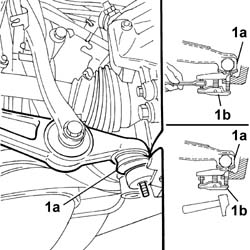
1. Undo the nuts fixing the track control arms to the steering knuckle.
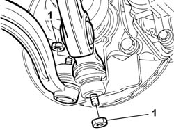
1. Extract the front track control arm head (1a) from the steering knuckle using a USAG-FACOM U.16A32 type extractor (1b) or a similar tool.
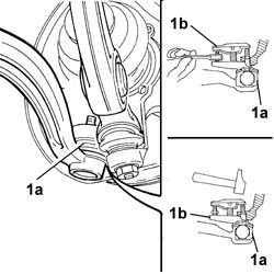
1. Extract the rear track control arm head (1a) from the steering knuckle using a USAG-FACOM U.16A32 type extractor (1b) or a similar tool.
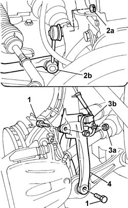
1. Undo the fixing bolts.
2. Undo the upper fixing nut (2a) and disconnect the end of the anti-roll bar connecting rod (2b).
3. Undo the fixing bolt (3a) and move the accelerometer sensor (3b), complete with mounting bracket, aside.
4. Remove the suspension fork.
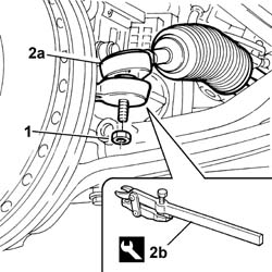
1. Undo the nut.
2. Extract the steering rod end (2a) using the extractor (2b).
| Description | Code | Function | |
|---|---|---|---|
| 2b | Head extractor | 1.847.035.000 | Extracting steering rod pin from stub axle |
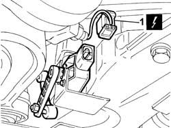
1. Disconnect the electrical connector for the headlamp alignment potentiometer.
| Description | Connector | |
|---|---|---|
| 1 | Headlamp alignment corrector front potentiometer (CAF) | K001 |
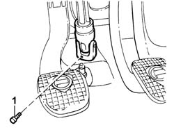
1. Working from inside the vehicle, undo the bolt fixing the lower steering conttol shaft to the steering box pinion.
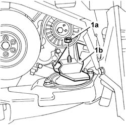
1. Undo the nut (1a) fixing the timing side rigid engine support (1b) to the flexible mounting.
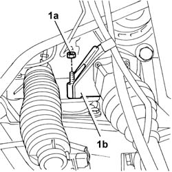
1. Undo the nut (1a) fixing the rigid rear support (1b) to the flexible mounting.
1. Position the tool for supporting the power unit-chassis assembly (1a), complete with hydraulic jack, under the housings in the engine support frame (1b).
| Description | Code | Function | |
|---|---|---|---|
| 1a | Power unit support frame | 1.870.835.000 | Removing-refitting power unit |
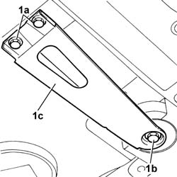
1. Undo the two rear bolts (1a) and the front bolt (1b) fixing each of the two rear engine mounting brackets (1c).
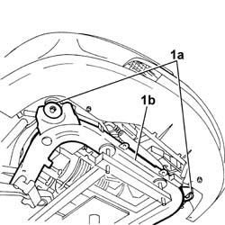
1. Undo the two front bolts (1a) fixing the frame (1b) to the bodyshell.
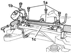
1. At the bench, undo the bolts (1a), disconnect the connector (1b) for the return pipe, then remove the power assisted steering box (1c).
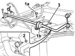
1. Undo the bolts (1a) fixing the u-bolts (1b) retaining the anti-roll bar.
2. Undo the nuts fixing the headlamp alignment corrector potentiometer connecting rod.
- Remove the anti-roll bar
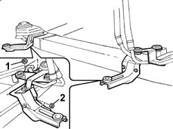
1. Undo the fixing nuts and remove the air filter mounting bracket.
2. Undo the fixing nuts and remove the engine cooling radiator mounting brackets.
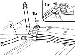
1. Undo the bolt (1a) and the nuts (1b) retaining the power assisted steering pipes mounting brackets.
2. Remove the power assisted steering system pipes.
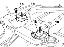
1. Undo the bolts (1a) and remove the front flexible mounting (1b) and the rear flexible mounting (1c).
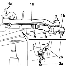
1. Undo the bolts (1a) and remove the track control arms (1b).
2. Undo the bolts (2a) and remove the headlamp alignment corrector potentiometer (2b).
Refitting
- Proceed with refitting the components removed at the bench.
- Fit the headlamp alignment corrector potentiometer.
- Fit the track control arms.
| Value - daNm | Fastening | Component | Ø | |
|---|---|---|---|---|
| (to the chassis) 10 | Bolt | LOWER FRONT TRACK CONTROL ARMS | M12 X 1.25 |
- Position the power assisted steering pipes and secure them using the mounting brackets.
- Position the engine cooling radiator mounting brackets.
- Position the air filter assembly mounting bracket and secure it to the crossmember using the fixing nuts.
- Connect the nut fixing the headlamp alignment corrector potentiometer connecting rod.
- Position the anti-roll bar and the retaining u-bolts, then tighten the fixing bolts on the crossmember to the recommended torque.
| Value - daNm | Fastening | Component | Ø | |
|---|---|---|---|---|
| 3.5 | Bolt | FRONT ANTI-ROLL BAR SUPPORTS | M8 |
- Position the power assisted steering box and fasten it to the frame tightening the bolts to the recommended torque.
| Value - daNm | Fastening | Component | Ø | |
|---|---|---|---|---|
| 11 | Bolt | COMPLETE POWER ASSISTED STEERING BOX | M12 X 1.25 |
| Value - daNm | Fastening | Component | Ø | |
|---|---|---|---|---|
| 1.5 | Bolt | COMPLETE POWER ASSISTED STEERING BOX | M8 |
- Connect the connector for the return pipe to the reservoir to the steering box.
| Value - daNm | Fastening | Component | Ø | |
|---|---|---|---|---|
| 3 | Bolt | RETURN PIPE TO POWER STEERING RESERVOIR | M12 X 1.5 |
- Position the front suspension crossmember, supported by the special tool, in the vehicle.
Fit the steering box pinion in the opening in the bodyshell.
- Position the reinforcement brackets, then tighten the bolts fixing the front suspension crossmember to the bodyshell to the recommended torque.
| Value - daNm | Fastening | Component | Ø | |
|---|---|---|---|---|
| 13 | Bolt | FRONT SUSPENSION SUBFRAME | M12 X 1.25 |
- Remove the tool supporting the front suspension frame.
| Description | Code | Function | |
|---|---|---|---|
| Power unit support frame | 1.870.835.000 | Removing-refitting power unit |
- Position a hydraulic lift under the engine, raise it slightly to allow the timing side flexible mounting to be fitted on the support, then tighten the bolts fixing it to the frame to the recommended torque.
The hydraulic lift only has to be raised slightly. Proceed very cautiously.
| Value - daNm | Fastening | Component | Ø | |
|---|---|---|---|---|
| (to the chassis) 5 | Bolt | FRONT FLEXIBLE MOUNTING BLOCKS, POWER UNIT | M10X 1.25 |
- Position a hydraulic lift under the engine, raise it slightly to allow the rear flexible mounting to be fitted on the support, then tighten the bolts fixing it to the frame to the recommended torque.
The hydraulic lift only has to be raised slightly. Proceed very cautiously.
| Value - daNm | Fastening | Component | Ø | |
|---|---|---|---|---|
| (to the chassis) 5 | Bolt | INTERM RUBBER MOUNT | M10X 1.25 |
- Tighten the nut fixing the timing side engine support to the flexible mounting.
| Value - daNm | Fastening | Component | Ø | |
|---|---|---|---|---|
| (to the flexible mounting) 5 | Nut | RIGID ENGINE MOUNT, TIMING SIDE | M10X 1.25 |
- Tighten the nut fixing the rear engine support to the flexible mounting.
| Value - daNm | Fastening | Component | Ø | |
|---|---|---|---|---|
| (to the flexible mounting) 5 | Nut | RIGID REAR SUPPORT POWER UNIT | M10 X 1.25 |
- Tighten the bolt fixing the lower steering conttol shaft to the steering box pinion.
| Value - daNm | Fastening | Component | Ø | |
|---|---|---|---|---|
| (to the steering box pinion) 2 | Bolt | FIXED ELEMENTS STEERING SHAFT STEERING | M8 |
- Connect the electrical connector for the headlamp alignment potentiometer.
| Description | Connector | |
|---|---|---|
| Headlamp alignment corrector front potentiometer (CAF) | K001 |
- Connect the steering rod ends and tighten the nuts fixing them to the steering knuckles to torque.
| Value - daNm | Fastening | Component | Ø | |
|---|---|---|---|---|
| (to the steering knuckle) 4.5 | Bolt | ADJUSTABLE STEERING ROD ENDS | M10 X 1.25 |
- Tighten the upper nut securing the anti-roll bar connecting rod end.
| Value - daNm | Fastening | Component | Ø | |
|---|---|---|---|---|
| 5.5 | Nut | FRONT ANTI-ROLL BAR JOINTS | M10 X 1.25 |
- Tighten the bolts fixing the fork to the steering knuckle.
| Value - daNm | Fastening | Component | Ø | |
|---|---|---|---|---|
| (to the lower front rod) 9 | Bolt | FRONT DAMPER FORK ON WISHBONE | M12 x 1.25 |
| Value - daNm | Fastening | Component | Ø | |
|---|---|---|---|---|
| (to the shock absorber) 11.6 | Bolt | FRONT DAMPER FORK ON WISHBONE | M12 X 1.25 |
- Position the bracket complete with accelerometer sensor and secure it using the bolt.
- Fit the front and rear track control arm heads to the steering knuckle and tighten the fixing nuts to the recommended torque.
| Value - daNm | Fastening | Component | Ø | |
|---|---|---|---|---|
| (to the steering knuckle) 9 | Nut | LOWER FRONT TRACK CONTROL ARMS | M14 X 1.5 |
| Value - daNm | Fastening | Component | Ø | |
|---|---|---|---|---|
| (to the steering knuckle) 8.8 | Nut | LOWER FRONT TRACK CONTROL ARMS | M12 X 1.25 |
- Remove the tools and the power unit mounting brackets.
| Description | Code | Function | |
|---|---|---|---|
| Crossmember | 1.870.595.000 | Power unit support |
| Description | Code | Function | |
|---|---|---|---|
| Support mountings | 1.870.650.000 | Power unit support |
| Description | Code | Function | |
|---|---|---|---|
| Crossmember | 1.860.851.003 | Power unit support |
| Description | Code | Function | |
|---|---|---|---|
| Vertical support | 1.870.748.000 | Power unit support |
- Reposition the cable loom on the left front suspension turret and secure it to the retaining band.
- Release the radiator-condenser-fan assembly from the upper crossmember.
- Connect the flexible and rigid sections of the return pipe to the power assisted steering reservoir; secure the pipes using the retaining band
See in Op. 1076B68 EXHAUST PIPE FLEXIBLE SECTION - R.R.
See in Op. 1076B50 Exhaust PIPE attachment to engine/manifold - R.R.
See in Op. 1076B70 EXHAUST PIPE BETWEEN PRECATALYZER AND CATALYZER - R.R.
See in Op. 1080B40 CATALYTIC PRECONVERTER - R.R.
See in Op. 1072C44 Exhaust manifold heat shield on BULKHEAD - R.R.
- Connect the connector on the steering box for the pressurized fluid supply pipe from the pump.
| Value - daNm | Fastening | Component | Ø | |
|---|---|---|---|---|
| 4 | Bolt | PIPE BTWN PUMP + POWER STEERING BOX | M14 X 1.5 |
- Connect the power assisted steering system pipes to the cooling coil.
See in Op. 1008C10 Power unit REACTION ROD - Replace
See in Op. 1088B10 Engine coolant SUPPLY RESERVOIR - R.R.
See in Op. 1048B14 air delivery pipe between turbo charger and heat exchanger - replace
See in Op. 1048A21 AIR INLET HOSE FROM INTAKE TO FILTER - R.R.
See in Op. 1048A50 air inlet pipe to turbocharger - r + r
See in Op. 1048A56 UPPER RESONATOR - R.R.
See in Op. 1048B44 RIGID air supply PIPE from heat exchanger to intake manifold - R.R.
See in Op. 1016A10 SOUND-PROOFING COVER - R.R.
See in Op. 1008C10 Power unit REACTION ROD - Replace
See in Op. 1088B10 Engine coolant SUPPLY RESERVOIR - R.R.
See in Op. 1048B14 air delivery pipe between turbo charger and heat exchanger - replace
See in Op. 1088E10 Radiator cooling FAN - R.R.
See in Op. 1048A10 COMPLETE AIR FILTER -R.R.
See in Op. 1048A50 air inlet pipe to turbocharger - r + r
See in Op. 1048A21 AIR INLET HOSE FROM INTAKE TO FILTER - R.R.
See in Op. 1016A40 Ignition COIL COVER on cylinder head - R.R.
See in Op. 1008C10 Power unit REACTION ROD - Replace
See in Op. 1048A10 AIR FILTER CASING - R.R.
See in Op. 1048A21 Cold AIR INTAKE PIPE for air filter - R.R.
See in Op. 1048A28 vacuum air circuit resonator pipe - r+r
See in Op. 1016A10 SOUND-PROOFING COVER - R.R.
See in Op. 1008C10 Power unit REACTION ROD - Replace
See in Op. 1048A10 COMPLETE AIR FILTER -R.R.
See in Op. 1048A21 AIR INLET HOSE FROM INTAKE TO FILTER - R.R.
See in Op. 1048A28 vacuum air circuit resonator pipe - r+r
See in Op. 1016A40 Ignition COIL COVER on cylinder head - R.R.
See in Op. 7210E10 FRONT BUMPER
See in Op. 7055B64 Engine compartment DUST SEAL in front wheel arch (one), left or right - R.R.
See in Op. 7055B42 FRONT WHEEL ARCH LINER (one), left or right - R.R.
See in Op. 4450B12 Front WHEELS (two) - R.R.
- Connect the negative battery lead.
See in Op. 0010T20 Engine REFRIGERANT FLUID - Change
See in Op. 7055B54 PROTECTION/GUARD under engine - R.R.
- Remove the vehicle from the lift.
- The power assisted steering system is self-bleeding, proceed as described below.
- Start the engine and carry out 4 -5 complete steering wheel rotation cycles (left and right).
- Top up the power assisted steering fluid level in the reservoir
Parts & tools for this job Staging For 2002 Lancia Thesis
- TOOLCoil spring compressorSearch: coil spring compressor
- TOOLBall joint separatorSearch: ball joint separator
- PARTFront shock absorbersSearch: Lancia Thesis 2002 front shock absorbers
Links open Amazon search results in a new tab. As an Amazon Associate I earn from qualifying purchases.