
Piston with connecting rod - r r
- Make
- Alfa Romeo
- Model
- GT Factory Service Manual
- Year
- 2003–2010
- Section
- Pistons and connecting rods › Piston with connecting rod - r r
PISTON WITH CONNECTING ROD - R R
Removing
Position the vehicle on a lift.
Make sure that the ignition key is in the OFF position, then disconnect the negative battery terminal (-).
| Description | Connector | |
|---|---|---|
| Battery | See A1B BATTERY ( BATTERY NEGATIVE ) |
Drain the air conditioning refrigerant circuit
Op. 0010T84 COOLANT FOR AIR CONDITIONING SYSTEM DEHYDRATE AND RECHARGE.
Proceed with the removal
Op. 4450B04 RIGHT FRONT WHEEL R R.
Proceed with the removal
Op. 7055B54 UNDER-ENGINE GUARD - R R.
Proceed with the removal
Op. 1016A40 IGNITION COIL COVER ON CYLINDER HEAD- R+R.
Proceed with the removal
Op. 5040A20 AIR CONDITIONER COMPRESSOR - R+R - INCLUDES FLUID LEVEL CHECK AND TOP UP IF NECESSARY.
Proceed with the removal
Op. 5040A26 COMPRESSOR MOUNT - R R.
Proceed with the removal
Op. 1076A48 CATALYTIC CONVERTER HEAT SHIELD - R R.
Proceed with the removal
Op. 1080B62 CATALYTIC CONVERTER - R + R.
Proceed with the removal
Op. 1016C10 SINGLE CYLINDER HEAD, REMOVED - OVERHAUL.
Proceed with the removal
Op. 1020A20 CRANK CASE OIL SUMP - R + R CLEAN SEALS FOR SEALANT APPLICATION.
Turn the crankshaft until the pistons of the 1st and 4th cylinder are set to BDC.
1. Undo the bolts (1a) and remove the connecting rod caps (1b) complete with half-bearings (1c) for cylinders 1 and 4.
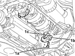
1. Withdraw and remove the piston/connecting rod assemblies (1a) complete with half-bearings (1b) for cylinders 1 and 4.
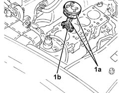
Work in the same way to remove the piston/connecting rod assemblies for cylinders 2 and 3.
Refitting
1. Place the piston/connecting rod assemblies (1a) for cylinders 2 and 3 complete with half-bearings (1b) in their housings using a suitable fitting tool.
The piston-connecting rod assemblies should be fitted so that the arrows stamped on the piston crown are facing the exhaust side.
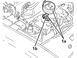
1. Place the connecting rod caps (1a) for cylinders 2 and 3 in their seats complete with half-bearings (1b) and secure them by tightening the bolts (1c) to the recommended torque.
The references on the connecting rod cap and the big end should be on the same side.
| Fastening | Component | Ø | Value (daNm) | |
|---|---|---|---|---|
| 1c | Bolt | CONNECTING ROD CAPS | M9 | 2.4 ÷ 2.6 +60? |
Use the tool for the angular tightening of the connecting rod cap bolts.
| Description | Code | |
|---|---|---|
| Torque wrench | 1.860.942.000 |
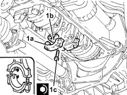
Work in the same way to fit the piston/connecting rod assemblies for cylinders 1 and 4.
Proceed with the refitting
Op. 1020A20 CRANK CASE OIL SUMP - R + R CLEAN SEALS FOR SEALANT APPLICATION.
Proceed with the refitting
Op. 1016C10 SINGLE CYLINDER HEAD, REMOVED - OVERHAUL.
Proceed with the refitting
Op. 1080B62 CATALYTIC CONVERTER - R + R.
Proceed with the refitting
Op. 1076A48 CATALYTIC CONVERTER HEAT SHIELD - R R.
Proceed with the refitting
Op. 5040A26 COMPRESSOR MOUNT - R R.
Proceed with the refitting
Op. 5040A20 AIR CONDITIONER COMPRESSOR - R+R - INCLUDES FLUID LEVEL CHECK AND TOP UP IF NECESSARY.
Proceed with the refitting
Op. 1016A40 IGNITION COIL COVER ON CYLINDER HEAD- R+R.
Proceed with the refitting
Op. 7055B54 UNDER-ENGINE GUARD - R R.
Proceed with the refitting
Op. 4450B04 RIGHT FRONT WHEEL R R.
Refill the air conditioning refrigerant circuit
Op. 0010T84 COOLANT FOR AIR CONDITIONING SYSTEM DEHYDRATE AND RECHARGE.
Connect the negative battery terminal (-).
Refill the engine cooling system
Remove the vehicle from the lift.
Removing
Position the vehicle on a lift.
Make sure that the ignition key is in the OFF position, then disconnect the negative battery terminal (-).
| Description | Connector | |
|---|---|---|
| Battery | See A1B BATTERY ( BATTERY NEGATIVE ) |
Proceed with the removal
Op. 1008C10 POWER UNIT UPPER REACTION LINK R R.
Proceed with the removal
Op. 1060G80 DS ELECTRIC INJECTION CONTROL UNIT - R R.
Proceed with the removal
Op. 4450B04 RIGHT FRONT WHEEL R R.
Proceed with the removal
Op. 7055B54 UNDER-ENGINE GUARD - R R.
Proceed with the removal
Op. 7055B91 RIGHT FRONT WHEEL ARCH LINER - R.R..
Proceed with the removal
Op. 1092G10 SINGLE ENGINE BELT R R.
Proceed with the removal
Op. 1092A10 CRANKSHAFT SERVICES PULLEY - R.R..
Proceed with the removal
Op. 1092G20 ENGINE COMPONENT SINGLE BELT FIXED TENSIONER - ONE - R + R.
Proceed with the removal
Op. 1032D12 TIMING SYSTEM PROTECTIVE COVER(S) - R + R.
Proceed with the removal
Proceed with the removal
Op. 1016C10 SINGLE CYLINDER HEAD, REMOVED - OVERHAUL.
1. Undo the plug and drain the engine oil.
Collect the engine oil in a suitable container. The engine oil used contains substances that are harmful to the environment. Place these substances in containers designed for oil collection and disposal.
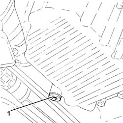
1. Undo the bolt connecting the intermediate driveshaft bearing support to the crankcase sump.
2. Undo the bolts fixing the manual gearbox-differential unit to the crankcase sump.
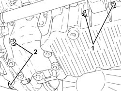
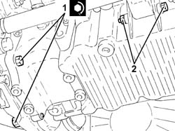
1. Undo the front and rear bolts (1a) fixing the crankcase sump using the tool (1b).
| Description | Code | |
|---|---|---|
| 1b | Spanner | 1.860.833.001 |
2. Undo the side bolts (2a) fixing the crankcase sump using the tool (2b).
| Description | Code | |
|---|---|---|
| 2b | Spanner | 1.860.834.001 |
3. Cut the crankcase sump sealant using the tool.
| Description | Code | |
|---|---|---|
| 3 | Blade | 1.870.718.000 |
4. Remove the crankcase sump.
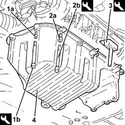
1. Undo the bolts (1a) and remove the connecting rod caps (1b) complete with half-bearings (1c).
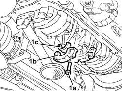
1. Release and remove the piston/connecting rod assemblies (1a) complete with half-bearings (1b).
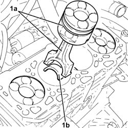
Refitting
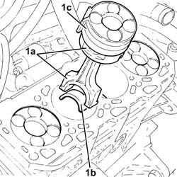
1. Place the piston/connecting rod assemblies (1a) in their housings complete with half-bearings (1b) using a suitable fitting tool (1c).
The piston-connecting rod assemblies should be fitted in the cylinder block/crankcase so that the drain on the piston skirt is aligned with the oil jet on the engine block.
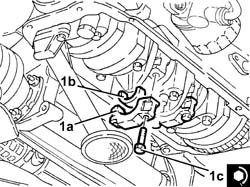
1. Place the bearing caps (1a) in their seats complete with half-bearings (1b) and secure them by tightening the bolts (1c) to the recommended torque.
Fit the connecting rods so that the number stamped on each rod faces towardt he same side as the number stamped on the big end (inlet side).
| Fastening | Component | Ø | Value (daNm) | |
|---|---|---|---|---|
| 1c | Bolt | CONNECTING ROD CAPS | M9 | 2.4 ÷ 2.6 + 60? |
Use the tool for the angular tightening of the connecting rod cap bolts.
| Description | Code | |
|---|---|---|
| Torque wrench | 1.860.942.000 |
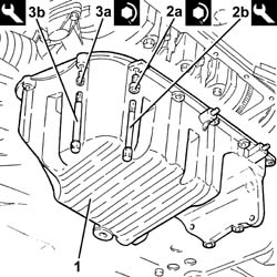
Thoroughly clean traces of sealant of the mating surfaces between the crankcase sump and engine block.
Apply silicon sealant to the entire perimeter of the crankcase sump.
1. Place the crankcase sump in its housing.
When positioning the crankcase sump, avoid significant sideways movements that could remove the sealant.
2. Tighten the side bolts (2a) fixing the crankcase sump to the recommended torque using the tool (2b).
| Fastening | Component | Ø | Value (daNm) | |
|---|---|---|---|---|
| 2a | Side bolts | OIL SUMP | M8 | (Engine crankcase side) 2.3 - 2.8 |
| Description | Code | |
|---|---|---|
| 2b | Spanner | 1.860.834.001 |
3. Tighten the front and rear bolts (3a) fixing the crankcase sump to the recommended torque using the tool (3b).
| Fastening | Component | Ø | Value (daNm) | |
|---|---|---|---|---|
| 3a | Front and rear bolt | OIL SUMP | M6 | (Front/rear cranckase covder side) 0.8 - 1.0 |
| Description | Code | |
|---|---|---|
| 3b | Spanner | 1.860.833.001 |
1. Tighten the bolts fixing the manual gearbox-differential unit to the crankcase sump to the specified torque.
| Fastening | Component | Ø | Value (daNm) | |
|---|---|---|---|---|
| 1 | Bolt | OIL SUMP | M10 | (Manual gearbox side) 5.0 - 6.1 |
2. Tighten the bolt connecting the intermediate driveshaft bearing support to the crankcase sump.
Fit a new engine oil drain plug complete with gasket and tighten it to the recommended torque.
| Fastening | Component | Ø | Value (daNm) |
|---|
Proceed with the refitting
Op. 1016C10 SINGLE CYLINDER HEAD, REMOVED - OVERHAUL.
Proceed with the refitting
Proceed with the refitting
Op. 1032D12 TIMING SYSTEM PROTECTIVE COVER(S) - R + R.
Proceed with the refitting
Op. 1092G20 ENGINE COMPONENT SINGLE BELT FIXED TENSIONER - ONE - R + R.
Proceed with the refitting
Op. 1092A10 CRANKSHAFT SERVICES PULLEY - R.R..
Proceed with the refitting
Op. 1092G10 SINGLE ENGINE BELT R R.
Proceed with the refitting
Op. 7055B91 RIGHT FRONT WHEEL ARCH LINER - R.R..
Proceed with the refitting
Op. 7055B54 UNDER-ENGINE GUARD - R R.
Proceed with the refitting
Op. 4450B04 RIGHT FRONT WHEEL R R.
Proceed with the refitting
Op. 1060G80 DS ELECTRIC INJECTION CONTROL UNIT - R R.
Proceed with the refitting
Op. 1008C10 POWER UNIT UPPER REACTION LINK R R.
Refill the engine oil lubrication system
Op. 0010T11 ENGINE OIL CHECK LEVEL AND TOP UP.
Refill the engine cooling system
Op. 0010T20 COOLANT CHECK DENSITY AND TOP UP IF NECESSARY.
Connect the negative battery terminal (-).
Remove the vehicle from the lift.
Removing
Position the vehicle on a lift.
Make sure that the ignition key is in the OFF position, then disconnect the negative battery terminal (-).
| Description | Connector | |
|---|---|---|
| Battery | Vedere A1B BATTERIA ( CABLAGGI ) |
Proceed with the removal
Op. 4450B04 RIGHT FRONT WHEEL R R
Proceed with the removal
Op. 7055B66 ENGINE COMPARTMENT DUST SHIELD PROTECTION IN RIGHT FRONT WHEEL ARCH - R.R.
Proceed with the removal
Op. 1016A40 IGNITION COIL COVER ON CYLINDER HEAD- R+R.
Proceed with the removal
Op. 5510C14 ROCCHETTI/BOBINE DI ACCENSIONE - S.R.
Proceed with the removal
Op. 1016A20 SINGLE CAM COVER - R + R AND REPLACE GASKET.
Proceed with the removal
Op. 1056B60 TUBO COLLETTORE COMBUSTIBILE UNICO, COMPLETO DI ELETTROINIETTORI - S.R.
Proceed with the removal
Op. 1072D10 MODULAR INLET MANIFOLD - R+R.
Proceed with the removal
Op. 1072C44 EXHAUST MANIFOLD HEAT SHIELD ON BULKHEAD - R+R.
Proceed with the removal
Op. 1092G10 SINGLE ENGINE BELT R R.
Proceed with the removal
Op. 1092G20 ENGINE COMPONENT SINGLE BELT FIXED TENSIONER - ONE - R + R.
Proceed with the removal
Op. 1092A10 CRANKSHAFT SERVICES PULLEY - R.R..
Proceed with the removal
Op. 1032D12 TIMING SYSTEM PROTECTIVE COVER(S) - R + R.
Proceed with the removal
Op. 1032B10 TOOTHED TIMING BELT - R + R FOR TIMING ADJUSTMENT OR REPLACEMENT.
Proceed with the removal
Op. 1016C10 SINGLE CYLINDER HEAD, REMOVED - OVERHAUL.
Proceed with the removal
Op. 1080B40 CATALYTIC PRE-CONVERTER - R R.
Proceed with the removal
Op. 1008A44 REAR RIGID MOUNT - R R.
Proceed with the removal
Op. 1020A20 CRANK CASE OIL SUMP - R + R CLEAN SEALS FOR SEALANT APPLICATION.
Turn the crankshaft until the pistons of the 1st and 4th cylinder are set to BDC.
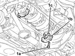
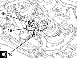
1. Undo the bolts (1a) and remove the connecting rod caps (1b) complete with half-bearings (1c) for cylinders 1 and 4.
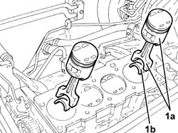
1. Withdraw and remove the piston/connecting rod assemblies (1a) complete with half-bearings (1b) for cylinders 1 and 4.
Work in the same way to remove the piston/connecting rod assemblies for cylinders 2 and 3.
Refitting
1. Place the piston/connecting rod assemblies (1a) for cylinders 2 and 3 complete with half-bearings (1b) in their housings using a suitable fitting tool (1c).
The pistons and connecting rods are fitted in the cylinder block/crankcase with the large grooves (for the inlet valves) on the piston crown facing the inlet side.
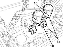
1. Place the connecting rod caps (1a) for cylinders 2 and 3 in their seats complete with half-bearings (1b) and secure them by tightening the bolts (1c) to the recommended torque.
Fit the connecting rods so that the number stamped on each rod faces towar the same side as the number stamped on the big end.
| Fastening | Component | Ø | Value (daNm) | |
|---|---|---|---|---|
| 1c | Bolt | CONNECTING ROD CAPS | M9 | 2.4 ÷ 2.6 + 60? |
Use the angle wrench to tighten the connecting rod cap bolts through the specified angle.
| Description | Code | |
|---|---|---|
| Torque wrench | 1.860.942.000 |
Work in the same way to fit the piston/connecting rod assemblies for cylinders 1 and 4.
Proceed with the refitting
Op. 1020A20 CRANK CASE OIL SUMP - R + R CLEAN SEALS FOR SEALANT APPLICATION.
Proceed with the refitting
Op. 1008A44 REAR RIGID MOUNT - R R.
Proceed with the refitting
Op. 1080B40 CATALYTIC PRE-CONVERTER - R R.
Proceed with the refitting
Op. 1016C10 SINGLE CYLINDER HEAD, REMOVED - OVERHAUL.
Proceed with the refitting
Op. 1032B10 TOOTHED TIMING BELT - R + R FOR TIMING ADJUSTMENT OR REPLACEMENT.
Proceed with the refitting
Op. 1032D12 TIMING SYSTEM PROTECTIVE COVER(S) - R + R.
Proceed with the refitting
Op. 1092A10 CRANKSHAFT SERVICES PULLEY - R.R..
Proceed with the refitting
Op. 1092G20 ENGINE COMPONENT SINGLE BELT FIXED TENSIONER - ONE - R + R.
Proceed with the refitting
Op. 1092G10 SINGLE ENGINE BELT R R.
Proceed with the refitting
Op. 1072C44 EXHAUST MANIFOLD HEAT SHIELD ON BULKHEAD - R+R.
Proceed with the refitting
Op. 1072D10 MODULAR INLET MANIFOLD - R+R.
Proceed with the refitting
Op. 1056B60 TUBO COLLETTORE COMBUSTIBILE UNICO, COMPLETO DI ELETTROINIETTORI - S.R.
Proceed with the refitting
Op. 1016A20 SINGLE CAM COVER - R + R AND REPLACE GASKET.
Proceed with the refitting
Op. 5510C14 ROCCHETTI/BOBINE DI ACCENSIONE - S.R.
Proceed with the refitting
Op. 1016A40 IGNITION COIL COVER ON CYLINDER HEAD- R+R.
Proceed with the refitting
Op. 7055B66 ENGINE COMPARTMENT DUST SHIELD PROTECTION IN RIGHT FRONT WHEEL ARCH - R.R.
Proceed with the refitting
Op. 4450B04 RIGHT FRONT WHEEL R R
Connect the negative battery terminal (-).
Refill the engine oil lubrication system
Op. 0010T11 ENGINE OIL CHECK LEVEL AND TOP UP.
Remove the vehicle from the lift.
Parts & tools for this job Staging For 2003 Alfa Romeo GT
- PARTEngine gasket setSearch: Alfa Romeo GT 2003 engine gasket set
- TOOLTorque wrenchSearch: 3/8 inch torque wrench
- TOOLFeeler gauge setSearch: feeler gauge set
Links open Amazon search results in a new tab. As an Amazon Associate I earn from qualifying purchases.