
Single cylinder head, removed - overhaul
- Make
- Alfa Romeo
- Model
- GT Factory Service Manual
- Year
- 2003–2010
- Section
- Cylinder head/s › Single cylinder head, removed - overhaul
SINGLE CYLINDER HEAD, REMOVED - OVERHAUL
Removing
Position the vehicle on a lift.
PROCEED WITH DRAINING THE HIGH PRESSURE FUEL SYSTEM FOLLOWING THE INSTRUCTIONS GIVEN BELOW.
Start the engine.
Keep the engine idling for 2 minutes.
Detach the fuel pump relay.
Wait until the engine cuts out.
Try and start the engine: if the engine starts within 10 seconds wait for it to cut out, then try and start the engine again; if the engine does not start within 10 seconds, continue for another 5 seconds.
Wait for the engine to cool down.
Make sure that the ignition key is in the OFF position, then disconnect the negative battery terminal (-)
| Description | Connector | |
|---|---|---|
| Battery | See A1B BATTERY ( BATTERY NEGATIVE ) |
Drain the air conditioning coolant circuit
Proceed with the removal.
Proceed with the removal.
Proceed with the removal.
Proceed with the removal.
Proceed with the removal.
Proceed with the removal.
Proceed with the removal.
1. Undo the bolts (1a) and remove the protection (1b).
2. Fit the flywheel lock.
| Description | Code | |
|---|---|---|
| 2 | Counter-torque | 1.860.898.000 |
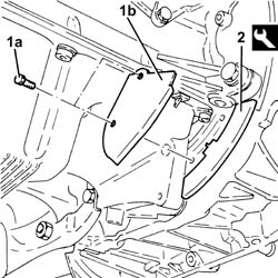
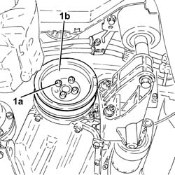
1. Undo the bolts (1a) and remove the crankshaft pulley (1b).
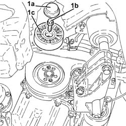
1. Remove plug (1a), unscrew bolt (1b) and remove the auxiliary drivebelt fixed tensioner (1c).
1. Undo the fixing bolts (1a) and remove the upper protective timing cover (1b).
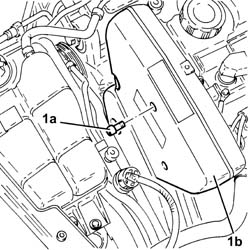
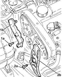
1. Undo the fixing bolts (1a) and remove the right side protective timing cover (1b).
2. Undo the fixing bolts (2a) and remove the left side protective timing cover (2b).
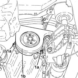
1. Undo the fixing bolts (1a) and remove the lower protective timing cover (1b).
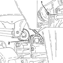
1. Slacken the counter-rotating shaft toothed belt.
2. Remove the counterrotating shaft toothed drive belt
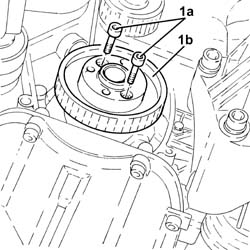
1. Undo the bolts (1a) and remove the counter-rotating shaft toothed belt drive pulley (1b).
Remove the flywheel lock.
| Description | Code | |
|---|---|---|
| Counter-torque | 1.860.898.000 |
1. Disconnect the electrical connections from the ignition coils.
| Description | Connector | |
|---|---|---|
| 1 | Ignition coil | See A30 IGNITION ''COIL |
2. Undo the bolts (2a) and remove the ignition coils (2b).
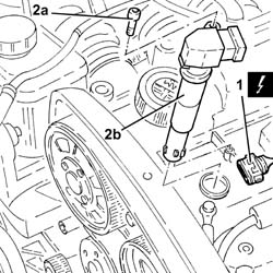
Remove the spark plug for cylinder no. 1.
1. Fit the tool (1a) complete with dial gauge (1b) in the seat for the spark plug for cylinder no. 1.
| Description | Code | |
|---|---|---|
| 1a | Extension | 1.860.895.001 |
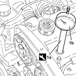
Working on the timing drive pulley fixing bolt, rotate the crankshaft in a clockwise direction until the piston for cylinder no.1 is at T.D.C. in the explosion stroke.
If TDC is exceeded, do not turn backwards but proceed with the rotation in the same direction rotating the crankshaft through another two revolutions and return the piston for cylinder no. 1 to TDC.
Remove the tool complete with dial gauge from the seat for the spark plug for cylinder no. 1.
| Description | Code | |
|---|---|---|
| Extension | 1.860.895.001 |
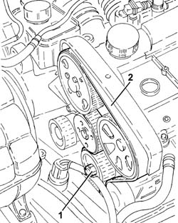
1. Loosen the moving timing tensioner nut.
2. Release and remove the toothed timing drive belt.
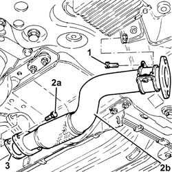
1. Undo the bolt fixing the rigid pipe mounting collar for the exhaust pipe between the catalytic converter and the silencer to the bracket.
2. Loosen the collar (2a) and remove the rigid pipe for the exhaust pipe between the catalytic converter and the silencer (2b).
3. Remove the seal.
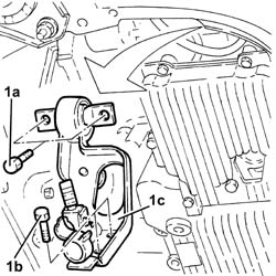
1. Undo bolts (1a), (1b) and remove the modular intake manifold bracket (1c) after releasing the strips connected to the bracket from the wiring.
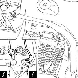
1. Disconnect the electrical connection from the knock sensor.
| Description | Connector | |
|---|---|---|
| 1 | Detonation sensor -1 | See K50 DETONATION SENSOR 1 ( CONNECTORS ) |
2. Disconnect the electrical connection from the insufficient engine oil pressure sensor.
| Description | Connector | |
|---|---|---|
| 2 | Engine oil pressure sensor (switch) | See K30 ENGINE OIL PRESSURE SENSOR SWITCH ( CONNECTORS ) |
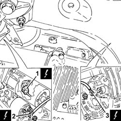
1. Disconnect the electrical connection from the rpm sensor.
| Description | Connector | |
|---|---|---|
| 1 | Rpm sensor | See K46 RPM SENSOR ( CONNECTORS ) |
2. Disconnect the earth lead from the starter motor.
| Description | Connector | |
|---|---|---|
| 2 | Starter motor | See A20 STARTER'' MOTOR |
3. Disconnect the earth lead from the alternator.
| Description | Connector | |
|---|---|---|
| 3 | Alternator | See A10 ALTERNATOR |
Proceed with the removal.
Proceed with the removal.
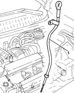
1. Withdraw the guide pipe and remve together with the engine oil dipstick.
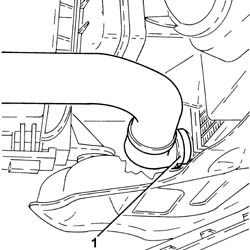
1. Disconnect the rapid connector for the lower coolant outlet hose from the radiator and drain the engine cooling system.
Manually press the clips and release the hose rapid connector.
Collect the coolant in a suitable container.
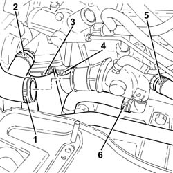
1. Loosen the collar and disconnect the upper coolant input sleeve to the radiator, thermostat side.
2. Loosen the collar and disconnect the coolant outlet pipe from the climate control system heater, on the side of the rigid pipe carrying coolant into the coolant pump.
3. Loosen the band and disconnect the lower coolant inlet hose from the radiator, water pump rigid coolant inlet pipe side.
4. Slacken the collar for the coolant outlet pipe from the engine oil heat exchanger on the water pump rigid inlet pipe side.
5. Loosen the collar and disconnect the coolant delivery pipe to the climate control system heater, thermostat side.
6. Loosen the collar and disconnect the coolant supply pipe to the engine oil heat exchanger, thermostat side.
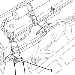
1. Loosen the band and disconnect the engine coolant system supply pipe from the water pump rigid inlet pipe.
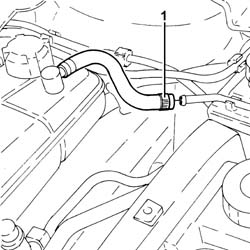
1. Loosen the collar and disconnect the flexible section from the rigid section of the coolant return pipe to the engine coolant reservoir.
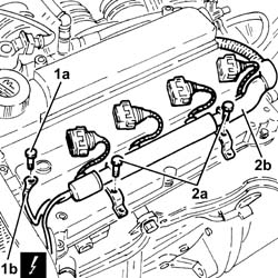
1. Undo the bolt (1a) and disconnect the earth lead (1b) from the cam cover.
| Description | Connector | |
|---|---|---|
| 1b | Earth on engine | See C40 ENGINE EARTH |
2. Undo the bolts (2a) and rmove the bulkhead coupling (2b) aside.
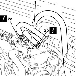
1. Disconnect the vacuum outlet pipe from the modular intake manifold.
2. Disconnect the engine wiring electrical connections (2a) and (2b).
| Description | Connector | |
|---|---|---|
| 2a | Front/engine coupling | See D4A FRONT/ENGINE CONNECTION ( CONNECTORS ) |
| Description | Connector | |
|---|---|---|
| 2b | Front/engine coupling | See D4B FRONT/ENGINE CONNECTION ( CONNECTORS ) |
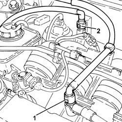
1. Disconnect the fuel supply pipe rapid connector.
2. Disconnect the rapid connector for the fuel vapour recovery pipe.
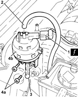
1. Disconnect the electrical connection from the switching control actuator enablement solenoid valve.
| Description | Connector | |
|---|---|---|
| 1 | Variable geometry solenoid valve | See L15 VARIABLE GEOMETRY CONTROL SOLENOID ( CONNECTORS ) |
2. Disconnect the vacuum intake pipe from the air flow switching device actuator and release it from the fastening on the latter.
3. Disconnect the air flow switching device actuator linkage.
4. Undo the bolts (4a) and remove the air flow switching device control actuator (4b).
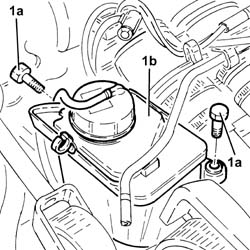
1. Undo the bolts (1a) and move the power assisted steering fluid reservoir (1b) sideways.
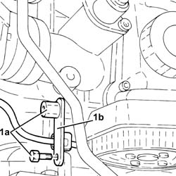
1. Undo bolts (1a) and remove bracket (1b) after releasing the band from the electrical wiring.
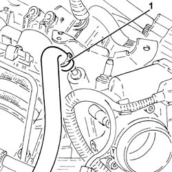
1. Loosen the band and disconnect the oil vapour recirculation pipe from the modular intake manifold.
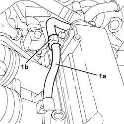
1. Release the pipe carrying fuel to the high pressure fuel pump (1a) from band (1b) on the cam cover.
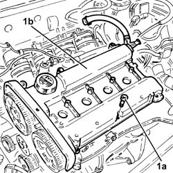
1. Undo the bolts (1a) and remove the cam cover (1b) complete with gasket.
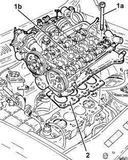
1. Undo the bolts (1a) and remove the cylinder head (1b).
Use commercial wrench USAG 233 1/2 S to loosen/tighten the cylinder head bolts.
2. Remove the cylinder head gasket.
Refitting
Ensure the cylinder head locating bushes are present on the crankcase.
Fit a new cylinder head gasket in position.
Position the cylinder head on the crankcase, ensuring that the cylinder 1 valves are closed.
Do not reuse the cylinder head bolts more than four times because they undergo permanent lengthening whenever they are tightened.
Replace the bolts if the number of times that the bolts have been tightenened to the cylinder head is unknown.
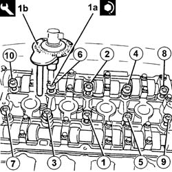
1. Tighten the cylinder head bolts (1a) to the recommended torque using the angular tightening tool (1b).
Follow the order shown in the figure for each tightening sequence.
Use commercial wrench USAG 233 1/2 S to loosen/tighten the cylinder head bolts.
| Fastening | Component | Ø | Value (daNm) | |
|---|---|---|---|---|
| 1a | Bolt | CYLINDER HEAD | M10 | (Engine crankcase side) 2 + 2 + 90° + 90° + 90° |
| Description | Code | |
|---|---|---|
| 1b | Torque wrench | 1.860.942.000 |
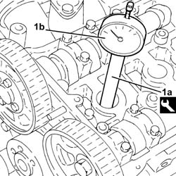
1. Fit the tool (1a) complete with dial gauge (1b) in the seat for the spark plug for cylinder no. 1.
| Description | Code | |
|---|---|---|
| 1a | Extension | 1.860.895.001 |
Rotate the crankshaft until the piston for cylinder no. 1 is at T.D.C. in the combustion stroke.
If TDC is passed, do not turn backwards but proceed with the rotation in the same direction rotating the crankshaft through another two revolutions and return the piston for cylinder no. 1 to TDC.
1. Undo the inlet side camshaft driven timing pulley bolts (1a) using the tool (1b) for counter-torque.
| Description | Code | |
|---|---|---|
| 1b | Counter-torque | 1.860.856.001 |
2. Undo the exhaust side driven timing pulley bolt (2a) using the tool (1b) for counter-torque.
| Description | Code | |
|---|---|---|
| 2b | Spanner for rotating timing pullies | 1.860.831.002 |
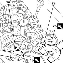
Undo the bolts and remove the inlet side camshaft fourth cap and the exhaust side camshaft second cap.
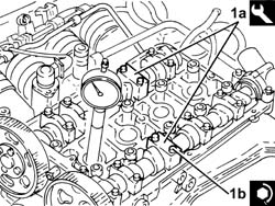
1. Fit the tool (1a) in place of the camshaft caps that have been removed and secure them tightening the bolts (1b) to the recommended torque.
Check that the camshaft cam profile and the tool are correctly aligned.
| Description | Code | |
|---|---|---|
| 1a | Templates | 1.870.859.000 |
| Fastening | Component | Ø | Value (daNm) | |
|---|---|---|---|---|
| 1b | Bolt | TEMPLATES FOR ENGINE TIMING | M7 | (Cylinder head side) 1.0 |
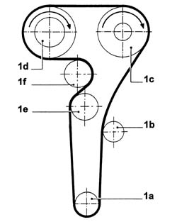
1. Fit the timing toothed drive belt in the following order:
toothed drive pulley (1a)
fixed tensioner (1b)
exhaust side toothed driven pulley (1c)
Before fitting the belt on the exhaust side driven toothed pulley, turn it clockwise (see figure) to the travel end stop.
inlet side toothed driven pulley (1d)
Before fitting the belt on the intake side driven toothed pulley, turn it clockwise (see figure) to the travel end stop.
moving tensioner (1e)
water pump pulley (1f).
The belt is fitted with the arrow facing the direction of rotation of the engine (clockwise - timing end).
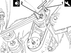
1. Use the tool to rotate the moving timing tensioner until the timing belt is completely taut.
| Description | Code | |
|---|---|---|
| 1 | Spanner | 1.822.149.000 |
2. Tighten the nut fixing the moving timing tensioner to the recommended torque.
| Fastening | Component | Ø | Value (daNm) | |
|---|---|---|---|---|
| 2 | Nut | MOBILE TIMING TENSIONER | M8 | 2.3 ÷ 2.8 |
1. Tighten the bolts (1a) for the inlet side toothed timing driven pulley to the specified torque using tool (1b) for counter-torque.
| Fastening | Component | Ø | Value (daNm) | |
|---|---|---|---|---|
| 1a | Bolt | TIMING DRIVEN PULLIES | M6 | (Inlet camshaft side) 0.8 - 1.0 |
| Description | Code | |
|---|---|---|
| 1b | Counter-torque | 1.860.856.001 |
2. Tighten the exhaust side driven timing pulley bolt (2a) using the tool (1b) for counter-torque.
| Fastening | Component | Ø | Value (daNm) | |
|---|---|---|---|---|
| 2a | Bolt | TIMING DRIVEN PULLIES | M12 | (Exhaust camshaft side) 10.8 - 13.2 |
| Description | Code | |
|---|---|---|
| 2b | Spanner for rotating timing pullies | 1.860.831.002 |
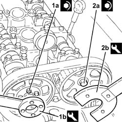
Remove the camshaft timing tools.
| Description | Code | |
|---|---|---|
| Templates | 1.870.859.000 |
Place the camshaft caps previously removed in their housings and secure them tightening the bolts to the recommended torque.
| Fastening | Component | Ø | Value (daNm) | |
|---|---|---|---|---|
| Bolt | CAMSHAFT CAPS | M7 | (Cylinder head side) 1.4 - 1.7 |
Turn the crankshaft through two turns in its direction of rotation (clockwise - timing end) and move the piston of cylinder 1 to TDC.
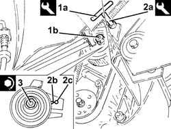
1. Insert tool (1a) to hold the mobile timing belt tensioner and loosen tensioner nut (1b).
| Description | Code | |
|---|---|---|
| 1a | Spanner | 1.822.149.000 |
2. Turn tool (2a) anticlockwise (timing end) to align tensioner mobile pointer (2b) with reference hole (2c).
| Description | Code | |
|---|---|---|
| 2a | Spanner | 1.822.149.000 |
3. Tighten the nut fixing the moving timing tensioner to the recommended torque.
| Fastening | Component | Ø | Value (daNm) | |
|---|---|---|---|---|
| 3 | Nut | MOBILE TIMING TENSIONER | M8 | 2.3 ÷ 2.8 |
Turn the crankshaft through two turns in its direction of rotation (clockwise - timing end) to move cylinder 1 to TDC in the combustion phase and use the tool to check that engine timing is correct.
| Description | Code | |
|---|---|---|
| Templates | 1.870.859.000 |
Remove the tool for checking T.D.C. from the housing for the spark plug for cylinder no.1.
| Description | Code | |
|---|---|---|
| Extension | 1.860.895.001 |
Place the spark plug for cylinder no.1 in its housing and tighten it to the recommended torque.
| Fastening | Component | Ø | Value (daNm) | |
|---|---|---|---|---|
| SPARK PLUGS | M14 | (Cylinder head side) 2.4 - 3.0 |
1. Position the counterrotating shaft toothed drive pulley (1a) in its housing and secure it tightening the bolt (1b) to the recommended torque.
| Fastening | Component | Ø | Value (daNm) | |
|---|---|---|---|---|
| 1b | Bolt | COUNTER-ROTATING SHAFT DRIVE PULLEY | M6 | (Timing drive pulley end) 0.8÷1.0 |
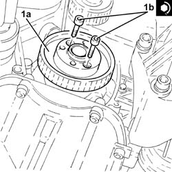
1. Turn the counter-rotating shafts so that notches (1a) on the pulleys are aligned with the ribs (1b).
2. Fi the lower timing system cover and the crankshaft pulley and check the alignment of the notches stamped on the parts.
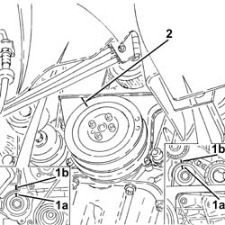
1. Fit the counterrotating shaft toothed drive belt
2. Tension the counterrotating shaft toothed drive shaft using tool (2a) to move reference hole (2b) on the tensioner to the middle of the rotation sector.
| Description | Code | |
|---|---|---|
| 2a | Spanner | 1.822.154.000 |
3. Tighten the nut fixing the toothed counter-rotating shaft belt tensioner to the recommended torque.
| Fastening | Component | Ø | Value (daNm) | |
|---|---|---|---|---|
| 3 | Nut | DRIVE BELT TENSIONER COUNTER-ROTATING SHAFT | M6 | (Left counterrotating shaft front cover end) 0.8 - 1.0 |
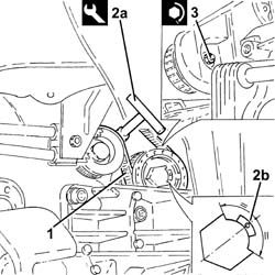
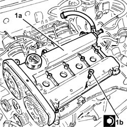
1. Place the cam cover (1a), complete with gasket, back in its housing and secure it tightening the bolts (1b) to the recommended torque.
| Fastening | Component | Ø | Value (daNm) | |
|---|---|---|---|---|
| 1b | Bolt | CAM COVER | M6 | (Cylinder head side) 0.8 - 1.0 |
Secure the pipe carrying fuel to the high pressure fuel pump to the band on the cam cover.
Connect the oil vapour recirculation pipe to the modular intake manifold and tighten the band.
Refit the bracket and secure with the bolts, then secure the electrical wiring to the band.
Place the power assisted steering fluid reservoir in its housing and secure it using the bolts.
Place the air flow switching device control actuator back in its housing and secure it using the bolts.
Connect the air flow switching device actuator linkage.
Connect the vacuum intake pipe from the air flow switching device actuator and secure it to the band on the latter.
Connect the electrical connection to the switching control actuator enablement solenoid valve.
Connect the rapid connector for the fuel vapour recovery pipe.
Connect the fuel supply pipe rapid connector.
Connect the electrical connections for the engine wiring.
Connect the vacuum outlet pipe to the modular intake manifold.
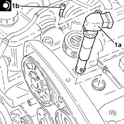
1. Replace the ignition coils (1a) in their housings and secure them tightening the bolts (1b) to the recommended torque.
| Fastening | Component | Ø | Value (daNm) | |
|---|---|---|---|---|
| 1b | Bolt | IGNITION COIL/REEL | M6 | (Cam cover side) 0.8 ÷ 1.0 |
Fit the bulkhead coupling in its housing and secure it using the bolts.
Connect the battery earth lead to the cam cover and secure it using the bolt.
Connect the electrical connections to the ignition coils.
Connect the flexible section to the rigid section of the coolant return pipe to the engine coolant reservoir and tighten the band.
Connect the engine coolant system supply pipe, water pump rigid inlet pipe side, and tighten the band.
Connect the coolant supply pipe to the engine oil heat exchanger, thermostat side, and tighten the band.
Connect the coolant delivery pipe to the climate control system heater, thermostat side, and tighten the band.
Connect the coolant outlet pipe from the climate control system heater, on the side of the rigid pipe carrying coolant into the coolant pump and tighten the collar.
Connect the lower coolant inlet hose from the radiator, water pump rigid coolant inlet pipe side and tighten the band.
Connect the coolant outlet pipe from the climate control system heater, on the side of the rigid pipe carrying coolant into the coolant pump and tighten the collar.
Connect the upper coolant input sleeve to the radiator, thermostat side, and tighten the band.
Connect the rapid connector for the radiator lower coolant outlet hose.
Refit the guide pipe and together with the engine oil dipstick.
Proceed with the refitting.
Proceed with the refitting.
Connect the earth lead to the starter motor.
Connect the earth lead to the alternator.
Connect the electrical connection to the insufficient engine oil pressure sensor.
Connect the electrical connection to the detonation sensor.
Connect the electrical connection to the rpm sensor.
Refit the modular intake manifold bracket and secure with bolts, then secure the wiring to the collars on the bracket.
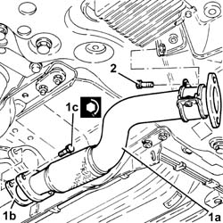
1. Place the rigid pipe for the exhaust pipe between the catalytic converter and the silencer (1a) complete with gasket (1b) back in its housing and secure it to the front exhaust silencer tightening the bolts (1c) to the recommended torque.
| Fastening | Component | Ø | Value (daNm) | |
|---|---|---|---|---|
| 1c | Bolt | RIGID EXHAUST PIPE | M8 |
2. Tighten the bolt fixing the rigid pipe mounting collar for the exhaust pipe between the catalytic converter and the silencer to the bracket.
Fit the lower timing belt cover and secure them using the bolts.
Fit theside timing belt covers and secure them using the bolts.
Fit the upper timing belt cover and secure it using the bolts.
1. Position the engine components single belt fixed tensioner (1a) in its housing and secure it tightening the bolt (1b) to the recommended torque.
| Fastening | Component | Ø | Value (daNm) | |
|---|---|---|---|---|
| 1b | Bolt | SINGLE BELT FIXED TENSIONER VARIOUS | M8 | 2.2 ÷ 2.8 |
2. Refit the plug on the auxiliary drivebelt tensioner
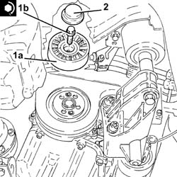
Fit the flywheel lock.
| Description | Code | |
|---|---|---|
| Counter-torque | 1.860.898.000 |
1. Position the crankshaft pulley (1a) in its housing and secure it tightening the bolts (1b) to the recommended torque.
| Fastening | Component | Ø | Value (daNm) | |
|---|---|---|---|---|
| 1b | Bolt | CRANKSHAFT PULLEY | M8 | 2.3 ÷ 2.8 |
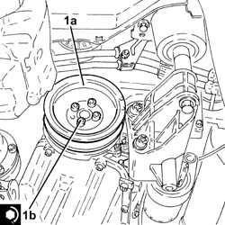
Remove the flywheel lock.
| Description | Code | |
|---|---|---|
| Counter-torque | 1.860.898.000 |
Fit the protection in its housing and secure it using the bolts.
Proceed with the refitting.
Proceed with the refitting.
Proceed with the refitting.
Proceed with the refitting.
Proceed with the refitting.
Proceed with the refitting.
Proceed with the refitting.
Refill the air conditioning coolant circuit
Connect the negative battery terminal (-).
Refill the engine cooling system
Remove the vehicle from the lift.
Removing
Position the vehicle on a lift.
Proceed with removal - 1016A10 SOUNDPROOFING COVER - R&R.
Make sure that the ignition key is in the OFF position, then disconnect the negative battery terminal (-)
| Description | Connector | |
|---|---|---|
| Battery | See A1B BATTERY ( BATTERY NEGATIVE ) |
Proceed with the removal
Op. 1008C10 POWER UNIT UPPER REACTION LINK R R.
Proceed with the removal
Op. 1060G80 DS ELECTRIC INJECTION CONTROL UNIT - R R.
Proceed with the removal
Op. 4450B04 RIGHT FRONT WHEEL R R.
Proceed with the removal
Op. 7055B54 UNDER-ENGINE GUARD - R R.
Proceed with the removal
Op. 7055B91 RIGHT FRONT WHEEL ARCH LINER - R.R..
Proceed with the removal
Op. 1092G10 SINGLE ENGINE BELT R R.
Proceed with the removal
Op. 1092A10 CRANKSHAFT SERVICES PULLEY - R.R..
Proceed with the removal
Op. 1092G20 ENGINE COMPONENT SINGLE BELT FIXED TENSIONER - ONE - R + R.
Proceed with the removal
Op. 1032D12 TIMING SYSTEM PROTECTIVE COVER(S) - R + R.
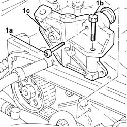
1. Undo bolts (1a) and (1b), then remove the bracket on the engine for reaction link (1c).
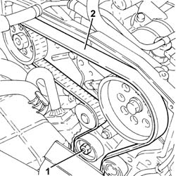
1. Loosen the nut retaining the timing belt moving tensioner.
2. Release and remove the toothed timing drive belt.
1. Loosen the band and disconnect the lower coolant inlet hose from the radiator, water pump rigid coolant inlet pipe side.
Collect the coolant that comes out in a suitable container.
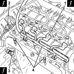
1. Disconnect the electrical connections from the injectors.
| Description | Connector | |
|---|---|---|
| 1 | Injector | See N70 INJECTOR |
2. Disconnect the electrical connection for the cam angle sensor.
| Description | Connector | |
|---|---|---|
| 2 | Timing sensor | See K47 TIMING SENSOR. ( CONNECTORS ) |
3. Disconnect the electrical connection for the air conditioner compressor.
| Description | Connector | |
|---|---|---|
| 3 | Air conditioning compressor engagement electro-magnet | See L20 AIR CONDITIONING COMPRESSOR ENGAGEMENT ELECTRO-MAGNET ( CONNECTORS ) |
Release the electrical wiring from the band on the timing cover.
4. Undo the bulkhead coupling bolts and move the electrical wiring aside.
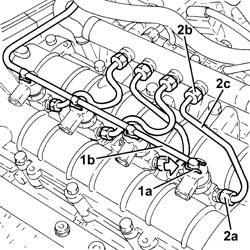
1. Push clips (1a) by hand and disconnect the pipe from the injectors to the fuel recovery manifold (1b), injector side, and move aside.
2. Unscrew the connectors (2a) and (2b) and remove the pipes from the fuel manifold to the injectors (2c).
Use new pipes from the fuel manifold to the injectors when refitting.
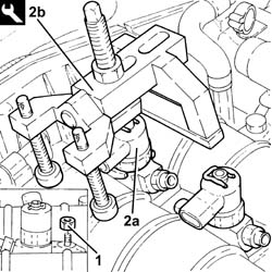
1. Undo the injector bracket retaining nuts.
2. Remove the injectors (2a) complete with brackets using the tools (2b).
If the injectors are being reused, mark the cylinder to which they belong so that they can be correctly refitted.
If a new injector/new inectors are fitted:
determine the identification code stamped on the top surface;
use an Examiner to initialise new injectors with the engine control unit.
Start the removal beginning with the injector for cylinder no. 1 and continue with the injectors for cylinders 2, 3, 4 and 5.
| Description | Code | |
|---|---|---|
| 2b | Extractor | 1.870.897.300 |
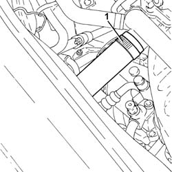
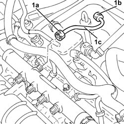
1. Undo the connectors (1a), (1b) and remove the pipe from the pressure pump to the fuel manifold (1c).
Use a new pipe from the pressure pump to the fuel manifold when refitting.
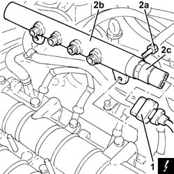
1. Disconnect the electrical connection from the fuel pressure sensor.
| Description | Connector | |
|---|---|---|
| 1 | Fuel pressure sensor | See K83 FUEL PRESSURE SENSOR |
2. Undo the bolts (2a) and remove the single fuel manifold pipe (2b) complete with fuel pressure sensor (2c).
Proceed with the removal
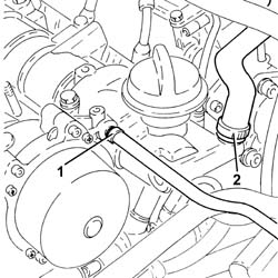
1. Loosen the band and disconnect the vacuum piping from the brake servo.
2. Loosen the band and disconnect the engine oil vapour recovery pipe from the engine oil filler.
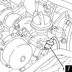
1. Disconnect the electrical connection from the engine coolant temperature sensor.
| Description | Connector | |
|---|---|---|
| 1 | Engine temperature sending unit | See K36 ENGINE TEMPERATURE SENDER UNIT ( CONNECTORS ) |
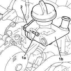
1. Undo the bolts (1a) and remove the engine oil filler (1b).
The bolts engine oil filler fitting have been treated with locking compound; therefore they should be replaced each time they are removed.
2. Remove the gasket.
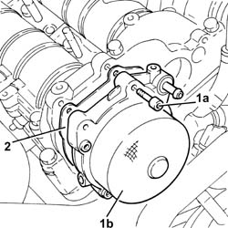
1. Undo the bolts (1a) and remove the vacuum unit (1b).
2. Remove the gasket.
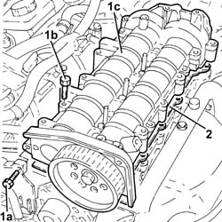
1. Undo the bolts (1a), (1b) and remove the cylinder head extension assembly (1c).
2. Remove the gasket.
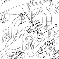
1. Remove the valve rockers.
2. Remove the hydraulic tappets.
1. Disconnect the glow plug electrical connections.
| Description | Connector | |
|---|---|---|
| 1 | Glow plugs | See A40 HEATER PLUGS (CYL. 1) |
2. Unscrew the glow plugs and remove.
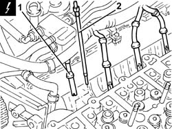
1. Disconnect the electrical connection for the turbocharger vane actuator solenoid valve.
| Description | Connector | |
|---|---|---|
| 1 | Turbine variable geometry control solenoid | See L36 VARIABLE GEOMETRY TURBINE SOLENOID VALVE ( CONNECTORS ) |
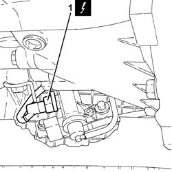
1. Disconnect the electrical connection from the air flow meter.
| Description | Connector | |
|---|---|---|
| 1 | Air flow meter | K41 |
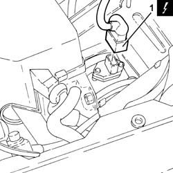
1. Disconnect the electrical connection for the EGR solenoid valve.
| Description | Connector | |
|---|---|---|
| 1 | EGR solenoid valve | See L30 EGR SOLENOID |
2. Disconnect the electrical connection for the pressure relief sensor.
| Description | Connector | |
|---|---|---|
| 2 | Turbocharging sensor | See K82 TURBOCHARGING SENSOR |
Release the wiring from the bands near the thermostat.
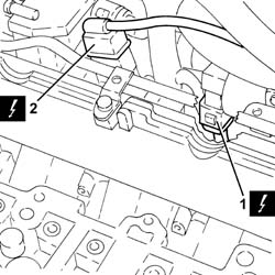
1. Loosen the collar and disconnect the coolant return pipe from the engine coolant reservoir, thermostat side.
2. Loosen the band and disconnect the coolant outlet pipe from the cylinder head, on the side of the coolant return pipe to the engine cooling reservoir.
3. Loosen the collar and disconnect the flexible pipe from the rigid coolant return pipe to the engine coolant reservoir.
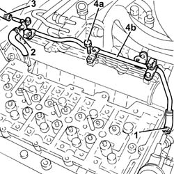
4. Undo botls (4a) and remove the coolant return pipe to the engine coolant reservoir (4b).
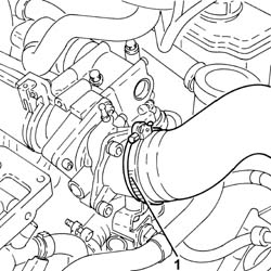
1. Loosen the band and disconnect the air inlet sleeve from the fitting on the throttle body.
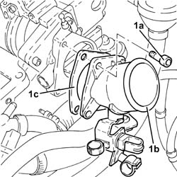
1. Undo the bolts (1a) and remove the fitting on throttle body (1b) complete with gasket (1c).
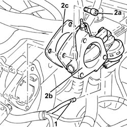
1. Disconnect the vacuum pipe for the pneumatic valve on the throttle body.
2. Undo the bolts (2a) and remove the electropneumatically controlled throttle body (2b) complete with gasket (2c).
Disconnect the vacuum pipe from the three-way fitting on the brake servo vacuum outlet pipe.
Disconnect the intermediate joint of the vacuum pipe for the turbocharger vane position actuator control solenoid.
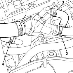
1. Loosen the collar and disconnect the upper coolant input sleeve to the radiator, thermostat side.
2. Loosen the collar and disconnect the coolant delivery pipe to the climate control system heater, thermostat side.
3. Loosen the collar and disconnect the coolant delivery pipe to the coolant/exhaust gas heat exchanger for the EGR system, thermostat side.
4. Loosen the collar and disconnect the coolant delivery pipe from the coolant/exhaust gas heat exchanger for the EGR system, heat exchanger side.
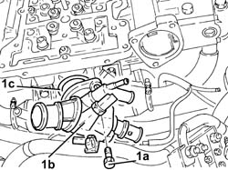
1. Undo the bolts (1a) and remove the thermostat (1b) complete with O-ring (1c).
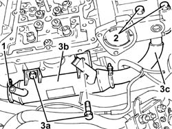
1. Loosen the collar securing the exhaust gas/coolant heat exchanger for the EGR system, exhaust gas intake side.
2. Undo the bolts fixing the E.G.R. system water/exhaust gas heat exchanger exhaust gas outlet pipe, EGR solenoid side.
3. Undo the bolts (3a) and remove the water/exhaust gas heat exchanger for the E.G.R. system (3b) complete with exhaust gas outlet pipe (3c).
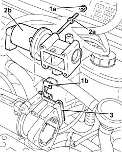
1. Undo nuts (1a) and move the oil vapour recovery pipe bracket (1b) to one side.
2. Undo the fixing bolts (2a) and remove the E.G.R. solenoid valve (2b).
3. Remove the gasket.
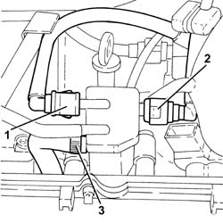
1. Disconnect the rapid connector for the fuel return pipe from the fuel filter, fuel return manifold pipe side.
2. Disconnect the rapid connector for the fuel return pipe to the tank, fuel return manifold pipe side.
3. Loosen the band and disconnect the fuel return pipe from the pressure pump, fuel return manifold pipe side.
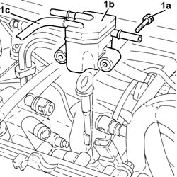
1. Undo the bolts (1a) and remove the fuel return manifold pipe (1b) with pipe from injectors to fuel return manifold (1c).
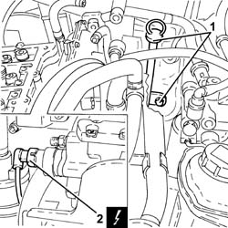
1. Undo the bolt securing the engine oil dipstick guide tube to the pressure pump mount.
2. Disconnect the electrical connection from the fuel pressure regulator.
| Description | Connector | |
|---|---|---|
| 2 | Fuel pressure regulator | See N77 FUEL PRESSURE REGULATOR ( CONNECTORS ) |
Release the electrical wiring from the band and move aside.
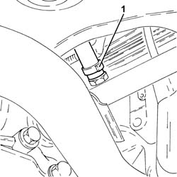
1. Loosen the band and disconnect the condensate oil recovery pipe from the crankcase sump.
1. Loosen the collar and disconnect the oil vapour recovery pipe from the separator.
2. Tighten the collar and disconnect the oil vapour recovery pipe from the separator.
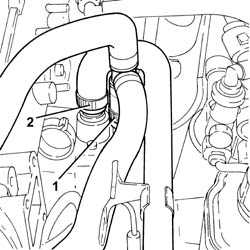
Disconnect the electrical connection for the solenoid valve on the vacuum reservoir.
| Description | Connector | |
|---|---|---|
| Throttle body solenoid valve | See L62 BUTTERFLY CASING SOLENOID VALVE |
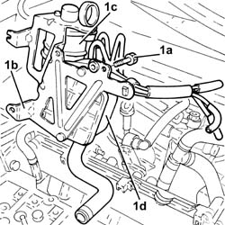
1. Undo botls (1a) and remove bracket (1b) with oil vapour separator (1c) and vacuum reservoir (1d).
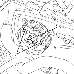
1. Lock the rotation of the pressure pump drive pulley using two bolts.
2. Undo the pressure pump drive pulley nut.
Undo the two bolts for locking the rotation of the pressure pump drive pulley fitted previously.
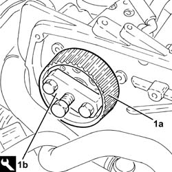
1. Remove the pressure pump drive pulley (1a) using the tools (1b).
| Description | Code | |
|---|---|---|
| 1b | Extractor | 1.860.854.001 |
1. Undo the nuts (1a) and remove the pressure pump (1b) from the support.
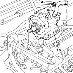
1. Disconnect the electrical connection from the engine oil pressure warning light switch.
| Description | Connector | |
|---|---|---|
| 1 | Engine oil pressure sensor (switch) | See K30 ENGINE OIL PRESSURE SENSOR SWITCH ( CONNECTORS ) |
2. Disconnect the electrical connection for the engine oil level sensor.
| Description | Connector | |
|---|---|---|
| 2 | Engine oil level sensor | See K32 ENGINE OIL LEVEL SENSOR |
3. Disconnect the electrical connection from the engine rpm sensor.
| Description | Connector | |
|---|---|---|
| 3 | Rpm sensor | See K46 RPM SENSOR ( CONNECTORS ) |
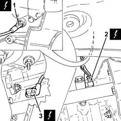
1. Disconnect the earth lead from the alternator.
| Description | Connector | |
|---|---|---|
| 1 | Alternator | See A10 ALTERNATOR |
2. Disconnect the earth lead from the starter motor.
| Description | Connector | |
|---|---|---|
| 2 | Starter motor | See A20 STARTER'' MOTOR |
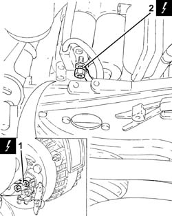
1. Disconnect the electrical connection for the glow plug control unit.
| Description | Connector | |
|---|---|---|
| 1 | Heater plugs control unit | See M15 PLUG PREHEATING CONTROL UNIT |
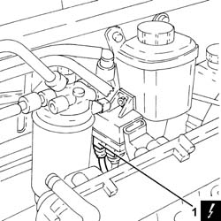
1. Undo the bolts (1a) and remove the power steering pump drive pulley (1b).
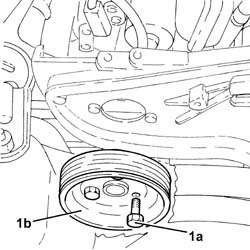
1. Undo the bolts securing the power steering pump to the mount.
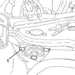
Remove the guide pipe together with the engine oil dipstick.
1. Undo the fixing bolts (1a) and remove the pressure pump mounting (1b).
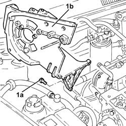
1. Undo the nuts (1a) and remove the air capacity chamber (1b) complete with gasket (1c).
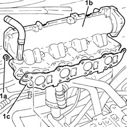
1. Loosen the band and disconnect the system supply pipe from the water pump rigid inlet pipe.
2. Loosen the collar and disconnect the coolant outlet pipe from the climate control system heater, on the side of the rigid pipe carrying coolant into the coolant pump.
3. Undo the bolts (3a) and remove the water pump inlet pipe (3b).
Remove the gasket.
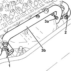
1. Undo the bolts (1a) and remove the exhaust pipe lower heat shield (1b).
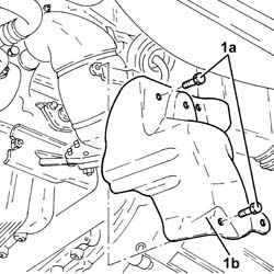
1. Undo the bolts (1a) and remove the exhaust pipe upper heat shield (1b).
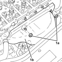
1. Undo the bolts fixing the front section of the exhaust pipe to the catalytic pre-converter.
2. Undo the bolts fixing the front section of the exhaust pipe to the catalytic converter.
3. Remove the front section of the exhaust pipe complete with gaskets.
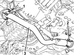
1. Disconnect the vacuum pipe from the variable geometry actuator.
2. Loosen the collar and disconnect the air delivery sleeve between the turbocharger and the heat exchanger, turbocharger side.
3. Loosen the collar and disconnect the corrugated air intake sleeve to the turbocharger, turbocharger side.
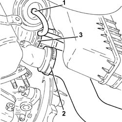
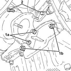
1. Undo bolts (1a) and nuts (1b) securing the catalytic preconverter bracket.
2. Undo the bolts securing the engine oil return pipe from the turbocharger, crankcase side.
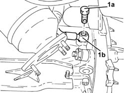
1. Undo the connector (1a) and disconnect the turbocharger oil supply pipe (1b), crankcase side.
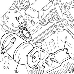
1. Loosen collar (1a) and remove catalytic preconverter (1b).
2. Retain the catalytic converter bracket.
1. Undo the nuts (1a) and remove the exhaust manifold (1b) complete with turbocharger (1c).
2. Remove the exhaust manifold gasket.
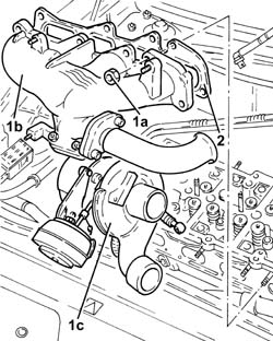
1. Undo the bolts (1a) and remove the lower cylinder head assembly (1b).
2. Remove the cylinder head gasket.
3. Remove the locating bushes.
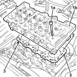
Refitting
1. Position the cylinder head locating bushes on the crankcase as shown in the figure.
The locating bushes between the crankcase and cylinder head are shorter (12.5 mm) than the bushes between the cylinder head and the cylinder head extension. Take gret care not to reverse them as this could impair engine operation.
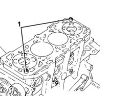
Fit a new cylinder head gasket taking care to ensure that it is the same size as the one removed.
Position the first cylinder at T.D.C.; rotate the crankshaft a further two teeth of the toothed timing drive pulley to lower the pistons thereby preventing any interference with the valves whilst fitting the cylinder head.
Position the cylinder head on the cylinder block/crankcase.
Do not reuse the cylinder head bolts more than four times because they undergo permanent lengthening whenever they are tightened. Replace the bolts if the number of times that the bolts have been tightenened to the cylinder head is unknown.
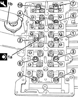
1. Tighten the cylinder head bolts (1a) to the recommended torque using the angular tightening tool (1b).
| Fastening | Component | Ø | Value (daNm) | |
|---|---|---|---|---|
| 1a | Bolt | CYLINDER HEAD | M12 | 2.0 + 4.5 + 90° + 90° + 90° |
| Description | Code | |
|---|---|---|
| 1b | Torque wrench | 1.860.942.000 |
Follow the order shown in the figure for each tightening sequence.
1. Place the exhaust manifold gasket in its housing.
2. Place the exhaust manifold (2a), complete with turbocharger, back in its housing and secure it tightening the nuts (2c) to the recommended torque.
| Fastening | Component | Ø | Value (daNm) | |
|---|---|---|---|---|
| 2c | Nut | EXHAUST MANIFOLD/S | M8 | (Cylinder head side) 2.3 - 2.8 |
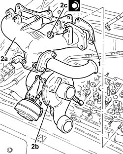
Refit the catalytic preconverter with bracket and secure to the turbocharger using the collar.
1. Connect the engine oil delivery pipe to turbocharger (1a), engine crankcase side, and tighten fitting (1b) to the specified torque.
| Fastening | Component | Ø | Value (daNm) | |
|---|---|---|---|---|
| 1b | Connector | OIL DELIVERY PIPE TO TURBO | M12 | (Engine crankcase side) 1.4 - 1.7 |
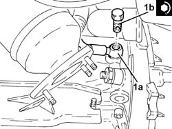
Undo the bolts securing the engine oil return pipe from the turbocharger, crankcase side.
Undo the bolts and nuts securing the catalytic preconverter bracket.
Connect the corrugated air intake sleeve to the turbocharger, turbocharger side, and tighten the band.
Connect the air delivery sleeve between the turbocharger and the heat exchanger, turbocharger side, and tighten the collar.
Disconnect the vacuum pipe to the variable geometry actuator.
1. Refit the front section of the exhaust pipe complete with gaskets.
2. Tighten the bolts fixing the front section of the exhaust pipe to the catalytic converter to the specified torque.
| Fastening | Component | Ø | Value (daNm) | |
|---|---|---|---|---|
| 2 | Nut | REACTION LINK ATTACHMENT BRACKET | M10 | (Bodyshell side) 4.2 - 5.2 |
3. Tighten the bolts fixing the front section of the exhaust pipe to the catalytic preconverter to the specified torque.
| Fastening | Component | Ø | Value (daNm) | |
|---|---|---|---|---|
| 3 | Nut | PIPE PRECATALYTIC CONVERTER/CATALYTIC CONVERTER | M8 | (Catalytic preconverter side) 2.3 ÷ 2.8 |
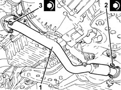
Place the upper exhaust manifold heat shield in its housing, then secure it using the nuts.
Place the lower exhaust manifold heat shield in its housing and secure it using the bolts.
Place the water pump rigid inlet pipe, complete with gasket, in position and secure it using the bolts.
Connect the coolant outlet pipe from the climate control system heater, on the side of the rigid pipe carrying coolant into the coolant pump and tighten the collar.
Connect the system supply pipe to the water pump rigid inlet pipe and tighten the band.
1. Refit the air capacity chamger (1a) complete with gasket (1b) back in its housing and secure it tightening the bolts (1c) to the recommended torque.
| Fastening | Component | Ø | Value (daNm) | |
|---|---|---|---|---|
| 1c | Nut | INLET MANIFOLD | M8 | (Cylinder head side) 2.3 - 2.8 |
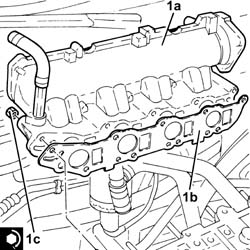
1. Fit the pressure pump mounting (1a) in its seat and secure it using the bolts (1b).
| Fastening | Component | Ø | Value (daNm) | |
|---|---|---|---|---|
| 1b | Bolt | INJECTION PRESSURE PUMP MOUNT | M8 | (Engine crankcase side) 2.3 - 2.8 |
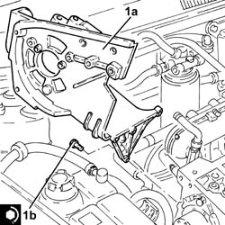
Refit the guide pipe and together with the engine oil dipstick.
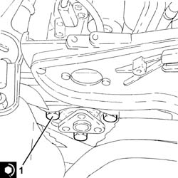
1. Position the power assisted steering pump in its housing and secure it tightening the bolts to the recommended torque.
| Fastening | Component | Ø | Value (daNm) | |
|---|---|---|---|---|
| 1 | Bolt | POWER STEERING PUMP | M8 | (Mount side) 2.3 - 2.8 |
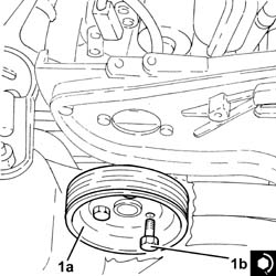
1. Position the power steering pump drive pulley (1a) in its housing and secure it tightening the bolt (1b) to the recommended torque.
| Fastening | Component | Ø | Value (daNm) | |
|---|---|---|---|---|
| 1b | Bolt | POWER STEERING PUMP DRIVE PULLEY | M8 | (Power assisted steering pump side) 2.3 - 2.8 |
Connect the electrical connection for the glow plug control unit.
Connect the earth lead to the starter motor.
Connect the earth lead to the alternator.
Connect the electrical connection for the engine rpm sensor.
Connect the electrical connection to the engine oil level sensor.
Connect the electrical connection to the engine oil pressure warning light switch.
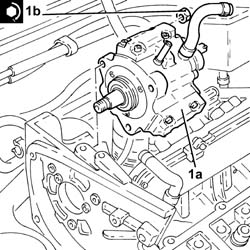
1. Position the pressure pump (1a) in its housing and secure it by tightening the nuts (1b) to the recommended torque.
| Fastening | Component | Ø | Value (daNm) | |
|---|---|---|---|---|
| 1b | Nut | PRESSURE PUMP | M8 | (Mount side) 2.3 - 2.8 |
1. Place the pressure pump drive pulley back in its housing.
2. Lock the rotation of the pressure pump drive pulley using two bolts.
3. Tighten the nut fixing the pressure pump drive pulley to the recommended torque.
| Fastening | Component | Ø | Value (daNm) | |
|---|---|---|---|---|
| 3 | Nut | PRESSURE PUMP CONTROL PULLEY | M14 | 4.5 ÷ 5.5 |
Undo the two bolts for locking the rotation of the pressure pump drive pulley fitted previously.
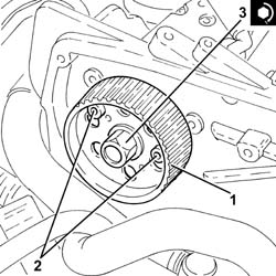
Refit the mounting bracket with oil vapour separator and vacuum reservoir and secure with the bolts.
Connect the electrical connection for the solenoid valve to the vacuum reservoir.
Connect the oil vapour recirculation hose to the separator and tighten the band.
Connect the oil vapour rrecovery hose to the separator and tighten the band.
Connect the condensate oil recovery pipe to the crankcase sump and tighten the band.
Refit the engine wiring and secure to the band.
Connect the electrical connection to the fuel pressure regulator.
Tighten the bolt securing the engine oil dipstick guide tube to the pressure pump mount.
Refit the fuel return manifold with pipe from the injectors to the fuel recovery manifold and secure with bolts.
Connect the fuel return pipe to the pressure pump, fuel return manifold side and tighten the band.
Connect the rapid connector for the fuel return pipe to the tank, fuel return manifold pipe side.
Connect the rapid connector for the fuel return pipe from the fuel filter, fuel return manifold pipe side.
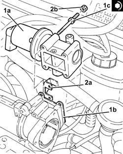
1. Fit the E.G.R. system solenoid valve (1a) complete with gasket (1b) and secure it tightening the bolts (1c) to the recommended torque.
| Fastening | Component | Ø | Value (daNm) | |
|---|---|---|---|---|
| 1c |
2. Place the oil vapour recover bracket (2a) back in its housing and fasten it using the nuts (2b).
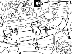
1. Refit the water/exhaust gas heat exchanger for the E.G.R. system (1a) complete with exhaust gas outlet pipe (1b).
2. Tightenthe bolts fixing the E.G.R. system water/exhaust gas heat exchanger exhaust gas outlet pipe, EGR solenoid side, to the specified torque.
| Fastening | Component | Ø | Value (daNm) | |
|---|---|---|---|---|
| 2 | Bolt | EGR WATER/EXHAUST GAS HEAT EXCHANGER | M8 | (EGR solenoid side) 2.3 - 2.8 |
3. Tighten the collar securing the exhaust gas/coolant heat exchanger for the EGR system, exhaust gas intake side.
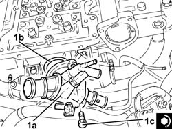
1. Place the thermostat (1a) in its housing with the o-ring (1b) and secure it by tightening the bolts (1c) to the recommended torque.
| Fastening | Component | Ø | Value (daNm) | |
|---|---|---|---|---|
| 1c |
Connect the coolant delivery pipe from the coolant/exhaust gas heat exchanger for the EGR system, heat exchanger side. and tighten the collar
Connect the coolant delivery pipe to the coolant/exhaust gas heat exchanger for the EGR system, thermostat side and tighten the collar.
Connect the coolant delivery pipe to the climate control system heater, thermostat side, and tighten the band.
Connect the upper coolant input sleeve to the radiator, thermostat side, and tighten the band.
Connect the intermediate joint of the vacuum pipe for the turbocharger vane position actuator control solenoid.
Connect the vacuum pipe to the three-way fitting on the brake servo vacuum outlet pipe.
1. Refit the intake electropneumatic throttle body (1a) complete with gasket (1b) back in its housing and secure it tightening the bolts (1c) to the recommended torque.
| Fastening | Component | Ø | Value (daNm) | |
|---|---|---|---|---|
| 1c |
2. Connect the vacuum pipe to the pneumatic valve on the throttle body.
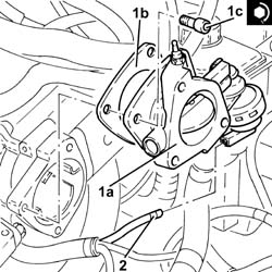
1. Refit the intake on the electropneumatic throttle body (1a) complete with gasket (1b) back in its housing and secure it tightening the bolts (1c) to the recommended torque.
| Fastening | Component | Ø | Value (daNm) | |
|---|---|---|---|---|
| 1c |
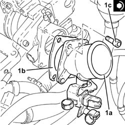
Connect the air intake sleeve to the throttle body and tighten the band.
Refit the coolant return pipe to the engien coolant tank and secure with bolts.
Connect the flexible pipe to the rigid coolant return pipe to the engine coolant reservoir to the coolant reservoir and tighten the collar.
Connect the coolant outlet pipe from the cylinder head, on the side of the coolant return pipe to the engine cooling reservoir, and tighten the collar.
Connect the coolant return pipe to the engine coolant reservoir to the coolant reservoir, thermostat side, and tighten the collar.
Secure the wiring to the bands near the thermostat.
Connect the electrical connection for the pressure relief sensor.
Connect the electrical connection for the E.G.R. solenoid valve.
Connect the electrical connection to the air flow meter.
Connect the electrical connection for the turbocharger vane actuator solenoid valve.
1. Refit the glow plugs and tighten them to the recommended torque.
| Fastening | Component | Ø | Value (daNm) | |
|---|---|---|---|---|
| 1 |
2. Connect the glow plug electrical connections.
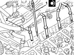
Place the hydraulic tappets in their housings.
Place the lower valve rockers in their housings.
1. Remove plug (1a) and fit camshaft timing tools (1b) to the cylinder head extension.
Check that the tools are correctly fitted in the housings in the camshafts.
| Description | Code | |
|---|---|---|
| 1b | Templates | 1.870.986.900 |
Remove the intake camshaft timing tool and tighten the plug.
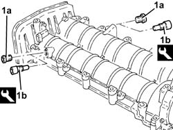
1. Position the cylinder head locating bushes on the cylinder head as shown in the figure.
The locating bushes between the crankcase and cylinder head are shorter (16.0 mm) than the bushes between the crankcase and the cylinder head. Take great care not to reverse them as this could impair engine operation.
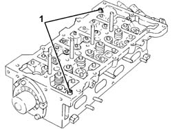
Refit the cylinder head extension gasket.
1. Position the cylinder head extension assembly (1a) in its housing and secure it by tightening the bolt (1b) to the recommended torque.
| Fastening | Component | Ø | Value (daNm) | |
|---|---|---|---|---|
| 1b | Bolt | CYLINDER HEAD EXTENSION | M8 | (Cylinder head side) 2.3 - 2.8 |
| Fastening | Component | Ø | Value (daNm) | |
|---|---|---|---|---|
| 1b | Bolt | INJECTION PRESSURE PUMP MOUNT | M8 | (Cylinder head side) 2.3 - 2.8 |
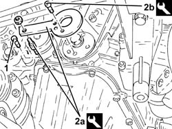
2. Loosen the bolt securing the exhaust side timing belt toothed drive pulley.
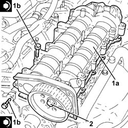
1. Undo the bolt fixing the crankcase front cover shown in the diagram.
Temporarily fit the toothed timing drive belt on the drive pulley.
2. Fit the tool (2a) and fasten it using the calibrated screw (2b).
The crankshaft must be rotated, using small movements, to allow the locating dowel on the timing drive pulley to be inserted in the opening in the tool.
| Description | Code | |
|---|---|---|
| 2a | Template | 1.860.905.000 |
| Description | Code | |
|---|---|---|
| 2b | Calibrated screw | 1.860.905.010 |
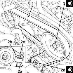
1. Fully fit the toothed timing drive belt.
2. Use a screwdriver for leverage in the opening (2a) until the reference for the tensioner (2b) is aligned with the opening reference (2c) and, in this position, tighten the nut (2d) for the belt tensioner to the recommended torque.
| Fastening | Component | Ø | Value (daNm) | |
|---|---|---|---|---|
| 2d | Nut | MOBILE TIMING TENSIONER | M8 | 2.3 ÷ 2.8 |
3. Tighten the bolt fixing the exhaust side camshaft toothed pulley to the recommended torque.
| Fastening | Component | Ø | Value (daNm) | |
|---|---|---|---|---|
| 3 | Bolt | TIMING DRIVEN PULLIES | M12 | (Exhaust camshaft side) 10.8 - 13.2 |
Remove the timing tools.
| Description | Code | |
|---|---|---|
| Templates | 1.870.986.900 |
emove the exhaust side camshaft template as the inlet side one has already been removed.
| Description | Code | |
|---|---|---|
| Template | 1.860.905.000 |
| Description | Code | |
|---|---|---|
| Calibrated screw | 1.860.905.010 |
Rotate the crankshaft through two revolutions.
Recheck the timing by refitting the timing tools.
nly fit the exhaust side camshaft template because the intake side template seat is not accessible.
Check the mobile timing belt tensioner references are aligned.
Tighten the bolt fixing the crankcase front cover removed previously.
Tighten the plug on the cylinder head extension for fitting the exhaust side timing tool.
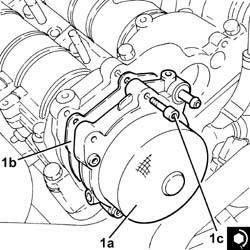
1. Place the vacuum pump (1a), complete with gasket (1b), back in its housing and secure it tightening the bolts (1c) to the recommended torque.
| Fastening | Component | Ø | Value (daNm) | |
|---|---|---|---|---|
| 1c | Bolt | BRAKING SYSTEM BRAKES | M6 | (Cylinder head side) 0.5 - 0.6 + 50? |
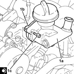
1. Refit the engine oil filler fitting (1a) complete with gasket (1b) back in its housing and secure it tightening the bolts (1c) to the recommended torque.
| Fastening | Component | Ø | Value (daNm) | |
|---|---|---|---|---|
| 1c | Bolt | OIL FILTER FITTING | M6 | (Cylinder head side) 0.8 - 1.0 |
Connect the electrical connection to the engine coolant temperature sensor.
Connect the engine oil vapour recovery pipe to the engine oil filler and tighten the band.
Connect the brake servo vacuum intake pipe and tighten the band.
Proceed with the refitting
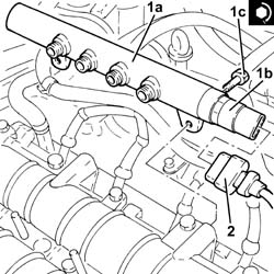
1. Fit the single fuel manifold pipe (1a) complete with fuel pressure sensor (1b) and secure it tightening the bolts (1c) to the recommended torque.
| Fastening | Component | Ø | Value (daNm) | |
|---|---|---|---|---|
| 1c | Bolt | INJECTOR FUEL MANIFOLD (DIESEL) | M8 | (Cylinder head extension side) 2.3 - 2.8 |
2. Connect the electrical connection to the fuel pressure sensor.
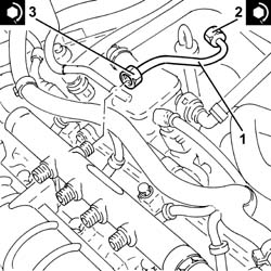
1. Place a new pipe from the pressure pump to the single fuel manifold in its housing and secure it using the connectors without tightening them.
2. Tighten the connector for the pipe from the pressure pump to the single fuel manifold, pump side, to the recommended torque using a spanner.
| Fastening | Component | Ø | Value (daNm) | |
|---|---|---|---|---|
| 2 | Connector | PRESSURE PUMP LINE TO FUEL MANIFOLD | M14 | (Pressure pump side) 2.2 - 2.4 |
3. Tighten the connector for the pipe from the pressure pump to the single fuel manifold, fuel manifold side, to the recommended torque using a spanner.
| Fastening | Component | Ø | Value (daNm) | |
|---|---|---|---|---|
| 3 | Connector | PRESSURE PUMP LINE TO FUEL MANIFOLD | M14 | (Fuel manifold side) 2.2 - 2.4 |
1. Fit the injectors (1a) in their seats complete with brackets and tighten the nuts (1b) to the recommended torque.
Start the removal beginning with the injector for cylinder no. 4 and continue with the injectors for cylinders 3, 2 and 1.
| Fastening | Component | Ø | Value (daNm) | |
|---|---|---|---|---|
| 1b | Nut | INJECTORS(DIESEL) | M8 | (Cylinder head extension side) 2.3 - 2.8 |
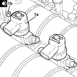
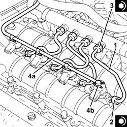
1. Fit new pipes from the fuel manifold to the injectors and secure with connectors without tightening.
2. Tighten the connectors for the pipes from the fuel manifold to the injector side injectors to the recommended torque using an appropriate commercial wrench.
| Fastening | Component | Ø | Value (daNm) | |
|---|---|---|---|---|
| 2 | Connector | PIPE FUEL MANIFOLD TO INJECTORS | M12 | (Injector side) 2.2 - 2.4 |
3. Tighten the connectors for the pipes from the fuel manifold to the fuel manifold side injectors to the recommended torque using an appropriate commercial wrench.
| Fastening | Component | Ø | Value (daNm) | |
|---|---|---|---|---|
| 3 | Connector | PIPE FUEL MANIFOLD TO INJECTORS | M12 | (Fuel manifold side) 2.2 - 2.4 |
Clean the threaded pipe seats on the manifold and injectors with heptane.
4. Connect the pipe from the injectors to the fuel recovery manifold (4a) to the injectors and push home until the clips (4b) click into place.
Place the electrical wiring in position and tighten the bulkhead coupling bolts.
Fasten the electrical wiring with the band on the timing cover.
Connect the electrical connection for the air conditioner compressor.
Connect the electrical connection for the cam angle sensor.
Connect the electrical connections to the injectors.
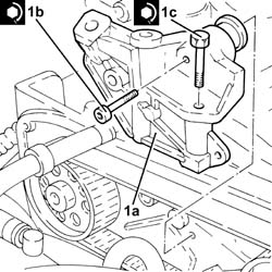
1. Position the bracket on the engine for reaction linkt (1a) in its housing and secure it tightening the bolts (1b) and (1c) to the recommended torque.
| Fastening | Component | Ø | Value (daNm) | |
|---|---|---|---|---|
| 1b | Bolt | REACTION LINK BRACKET ON ENGINE | M10 | (Cylinder head side) 4.5 - 5.5 |
| Fastening | Component | Ø | Value (daNm) | |
|---|---|---|---|---|
| 1c | Bolt | REACTION LINK BRACKET ON ENGINE | M10 | (Power assisted steering pump side) 4.5 - 5.5 |
Proceed with the refitting
Op. 1032D12 TIMING SYSTEM PROTECTIVE COVER(S) - R + R.
Proceed with the refitting
Op. 1092G20 ENGINE COMPONENT SINGLE BELT FIXED TENSIONER - ONE - R + R.
Proceed with the refitting
Op. 1092A10 CRANKSHAFT SERVICES PULLEY - R.R..
Proceed with the refitting
Op. 1092G10 SINGLE ENGINE BELT R R.
Proceed with the refitting
Op. 7055B91 RIGHT FRONT WHEEL ARCH LINER - R.R..
Proceed with the refitting
Op. 7055B54 UNDER-ENGINE GUARD - R R.
Proceed with the refitting
Op. 4450B04 RIGHT FRONT WHEEL R R.
Proceed with the refitting
Op. 1060G80 DS ELECTRIC INJECTION CONTROL UNIT - R R.
Proceed with the refitting
Op. 1008C10 POWER UNIT UPPER REACTION LINK R R.
Refill the engine cooling system
Op. 0010T20 COOLANT CHECK DENSITY AND TOP UP IF NECESSARY.
Proceed with refitting - 1016A10 SOUNDPROOFING COVER - R&R.
Connect the negative battery terminal (-).
Remove the vehicle from the lift.
Removing
Position the vehicle on a lift.
Proceed with the removal
Op. 5530B10 BATTERIA - S.R.
Proceed with the removal
Op. 4450B04 RIGHT FRONT WHEEL R R
Proceed with the removal
Op. 7055B66 ENGINE COMPARTMENT DUST SHIELD PROTECTION IN RIGHT FRONT WHEEL ARCH - R.R.
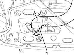
1. Disconnect the lower coolant outlet hose from the radiator and drain the engine cooling system.
Manually press the clips and release the hose rapid connector.
Collect the coolant in a suitable container.
Proceed with the removal
Op. 1016A40 IGNITION COIL COVER ON CYLINDER HEAD- R+R.
Proceed with the removal
Op. 5510C14 ROCCHETTI/BOBINE DI ACCENSIONE - S.R.
Proceed with the removal
Op. 1016A20 SINGLE CAM COVER - R + R AND REPLACE GASKET.
Proceed with the removal
Op. 1056B60 TUBO COLLETTORE COMBUSTIBILE UNICO, COMPLETO DI ELETTROINIETTORI - S.R.
Proceed with the removal
Op. 1072D10 MODULAR INLET MANIFOLD - R+R.
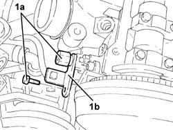
1. Undo bolts ( 1a) and remove bracket (1b) connecting the intake manifold to the bracket on the engine for the reaction link.
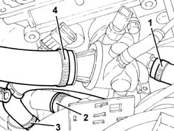
1. Disconnect the coolant delivery pipe to the climate control system heater, thermostat side.
2. Disconnect the coolant return pipe from the climate control system heater, on the side of the rigid pipe carrying coolant into the coolant pump.
3. Disconnect the flexible pipe from the rigid pipe carrying coolanta to the engine oil heat exchanger.
4. Disconnect the lower radiator coolant outlet hose.
Proceed with the removal
Op. 1072C44 EXHAUST MANIFOLD HEAT SHIELD ON BULKHEAD - R+R.
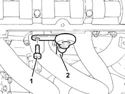
1. Undo the bolt securing the engine oil dipstick tube.
2. Remove the engine oil dipstick tube assembly.
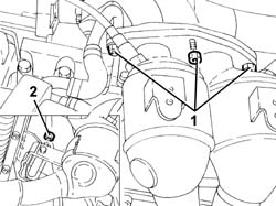
1. Undo the nuts fixing the catalytic preconverter to the exhaust manifold.
2. Undo the nuts fixing the catalytic preconverter to the exhaust manifold.
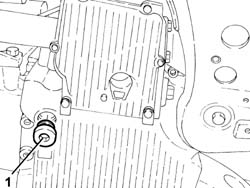
1. Undo the plug and drain the engine oil.
Collect the engine oil in a suitable container.
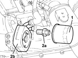
1. Undo and remove the engine oil filter using a suitable tool.
2. Unscrew pin (2a) and release engine oil heat exchanger (2b) from the crankshaft front sealing cover.
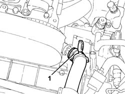
1. Disconnect the engine coolant system supply pipe from the water pump rigid inlet pipe.
Proceed with the removal
Op. 1092G10 SINGLE ENGINE BELT R R.
Proceed with the removal
Op. 1092A10 CRANKSHAFT SERVICES PULLEY - R.R..
Proceed with the removal
Op. 1092G20 ENGINE COMPONENT SINGLE BELT FIXED TENSIONER - ONE - R + R.
Proceed with the removal
Op. 1032D12 TIMING SYSTEM PROTECTIVE COVER(S) - R + R.
Proceed with the removal
Op. 1032B10 TOOTHED TIMING BELT - R + R FOR TIMING ADJUSTMENT OR REPLACEMENT.
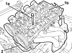
1. Undo the bolts (1a) and remove the cylinder head (1b).
Use commercial wrench USAG 233 1/2 S to loosen/tighten the cylinder head bolts.
2. Remove the cylinder head gasket.
Refitting
Fit a new cylinder head gasket in position.
The cylinder head gasket is ASTADUR type.
The material from which the gasket is made undergoes a polymerization process during the operation of the engine so that it becomes considerably harder during usage.
In order for the polymerization process to take place, it is necessary to:
- keep the gasket sealed in its casing until it is fitted;
- not lubricate the gasket or the contact surfaces with oil.
Position the cylinder head on the cylinder block/crankcase taking care to ensure that the camshafts are positioned with the front cams facing outwards (valves closed).
Do not reuse the cylinder head bolts more than four times because they undergo permanent lengthening whenever they are tightened. Replace the bolts if the number of times that the bolts have been tightenened to the cylinder head is unknown.
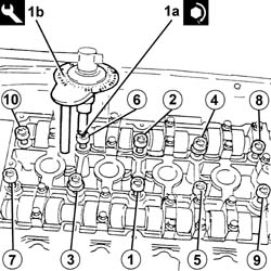
1. Tighten the cylinder head bolts (1a) to the recommended torque using the angular tightening tool (1b).
Follow the order shown in the figure for each tightening sequence.
Use commercial wrench USAG 233 1/2 S to loosen/tighten the cylinder head bolts.
| Fastening | Component | Ø | Value (daNm) | |
|---|---|---|---|---|
| 1a | Bolt | CYLINDER HEAD | M10 | 4.0+90°+90°+90° |
| Description | Code | |
|---|---|---|
| 1b | Torque wrench | 1.860.942.000 |
Achieve the figure of 4.0 daNm by a pretightening of 2.0 daNm subsequently increased by a torque of 2.0 daNm to achieve a nominal value of .0 daNm
Proceed with the refitting
Op. 1032B10 TOOTHED TIMING BELT - R + R FOR TIMING ADJUSTMENT OR REPLACEMENT.
Proceed with the refitting
Op. 1032D12 TIMING SYSTEM PROTECTIVE COVER(S) - R + R.
Proceed with the refitting
Op. 1092G20 ENGINE COMPONENT SINGLE BELT FIXED TENSIONER - ONE - R + R.
Proceed with the refitting
Op. 1092A10 CRANKSHAFT SERVICES PULLEY - R.R..
Proceed with the refitting
Op. 1092G10 SINGLE ENGINE BELT R R.
Connect the engine coolant system supply pipe to the water pump rigid inlet pipe.
Place the engine oil heat exchanger in its housing and secure it to the front crankcase sealing cover using the pin.
Fit the engine oil filter in its seat and tighten it fully by hand.
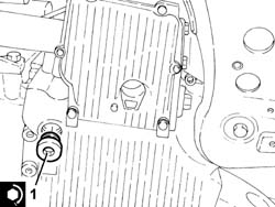
1. Tighten the engine oil drain plug to the recommended torque.
| Fastening | Component | Ø | Value (daNm) | |
|---|---|---|---|---|
| 1 | ENGINE OIL DRAIN PLUG | M18 | (Crankcase sump side) 1.8 - 2.2 |
Tighten the exhaust manifold front section nuts to the bracket.
Tighten the nuts fixing the catalytic preconverter to the exhaust manifold to the recommended torque.
| Fastening | Component | Ø | Value (daNm) | |
|---|---|---|---|---|
| Nut | CATALYTIC PRE-CONVERTER | M8 | (Manifold end) 2.7 - 3.3 |
Place the engine oil dipstick pipe back in its housing and fasten it with the bolt.
Proceed with the refitting
Op. 1072C44 EXHAUST MANIFOLD HEAT SHIELD ON BULKHEAD - R+R.
Connect the lower radiator coolant outlet hose.
Connect the flexible pipe from the rigid pipe carrying coolant to the engine oil heat exchanger.
Connect the coolant return pipe from the climate control system heater, on the side of the rigid pipe carrying coolant into the coolant pump.
Connect the coolant delivery pipe to the climate control system heater, thermostat side.
Refit the intake manfold connection bracket to the bracket on the engine for the reaction link and secure with the bolts.
Proceed with the refitting
Op. 1072D10 MODULAR INLET MANIFOLD - R+R.
Proceed with the refitting
Op. 1056B60 TUBO COLLETTORE COMBUSTIBILE UNICO, COMPLETO DI ELETTROINIETTORI - S.R.
Proceed with the refitting
Op. 1016A20 SINGLE CAM COVER - R + R AND REPLACE GASKET.
Proceed with the refitting
Op. 5510C14 ROCCHETTI/BOBINE DI ACCENSIONE - S.R.
Proceed with the refitting
Op. 1016A40 IGNITION COIL COVER ON CYLINDER HEAD- R+R.
Connect the lower radiator coolant outlet hose.
Proceed with the refitting
Op. 7055B66 ENGINE COMPARTMENT DUST SHIELD PROTECTION IN RIGHT FRONT WHEEL ARCH - R.R.
Proceed with the refitting
Op. 4450B04 RIGHT FRONT WHEEL R R
Proceed with the refitting
Op. 5530B10 BATTERIA - S.R.
Refill the engine oil lubrication system
Op. 0010T11 ENGINE OIL CHECK LEVEL AND TOP UP.
Refill the cooling system
Op. 0010T20 LIQUIDO REFRIGERANTE" MOTORE - Sost.
Remove the vehicle from the lift.
Parts & tools for this job Staging For 2003 Alfa Romeo GT
- PARTEngine gasket setSearch: Alfa Romeo GT 2003 engine gasket set
- TOOLTorque wrenchSearch: 3/8 inch torque wrench
- TOOLFeeler gauge setSearch: feeler gauge set
Links open Amazon search results in a new tab. As an Amazon Associate I earn from qualifying purchases.