
Piston connecting rod set - r r
- Make
- Alfa Romeo
- Model
- GT Factory Service Manual
- Year
- 2003–2010
- Section
- Pistons and connecting rods › Piston connecting rod set - r r
PISTON CONNECTING ROD SET - R R
Removing
1. Undo the plug and drain the engine oil.
Collect the engine oil in a suitable container.
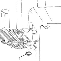
Rotate the engine through 180° on the overhaul stand.
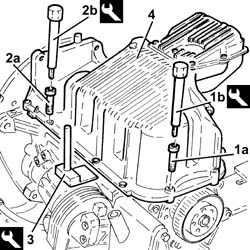
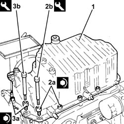
1. Undo the front and rear bolts (1a) fixing the crankcase sump using the tool (1b).
| Description | Code | |
|---|---|---|
| 1b | Spanner | 1.860.833.001 |
2. Undo the side bolts (2a) fixing the crankcase sump using the tool (2b).
| Description | Code | |
|---|---|---|
| 2b | Spanner | 1.860.834.001 |
3. Cut the crankcase sump sealant using the tool.
| Description | Code | |
|---|---|---|
| 3 | Blade | 1.870.718.000 |
4. Remove the crankcase sump.
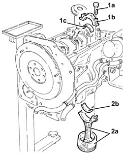
Turn the crankshaft by adjusting the bolt of the toothed drive pulley until the pistons of the 1st and 4th cylinder are set to BDC.
1. Undo the bolts (1a) and remove the connecting rod caps (1b) complete with half-bearings (1c) for cylinders 1 and 4.
2. Remove the cylinder 1 and 4 piston-connecting rod assemblies (2a) complete with half-bearings (2b)
Carry out the same operations to remove the connecting rod half-bearings for the remaining cylinders.
Refitting
This engine is fitted with main bearing and connecting rod bearing halves specially selected to achieve an optimised, instant mating clearance.
The crankshaft supplied by the Parts Dept. comes without half-bearings and the main journals and crankpins are the "normal" size; the half-bearings to be fitted must therefore be selected identifying the class of each main journal and crankpin for the new crankshaft.
The following must be determined for the selection of crankpin half-bearings:
- The numerical code stamped on the phonic wheel;
- the paint mark (if present) added in a position adjacent to the crankpins.
Below is an example of the identification of crankpin grades:
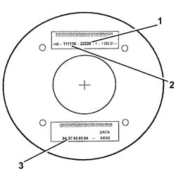
1 - Crankpin identification numerical code: the left hand number refers to the first timing side pin; the final "N" is a non-essential code for 4 cylinder engines.
2 - Main journal identification numerical code: the left hand number refers to the first timing side journal; the final "N" is a non-essential code for 4 cylinder engines.
3 - Series of numbers (if present), in groups of two digits, which indicate the dimensions (thousandth part) of the main journals: the first two numbers on the left refer to the first timing side journal.
Only use the codes that relate to the key, all other codes on the flywheel should not be used.
For the identification of the crankpin grade, refer to the numerical code for key reference 1.
In the case of the example, the numbers 2222N indicate that all six bearings are Grade B (blue) as indicated below.
CRANKPIN IDENTIFICATION
Category of crankpin A (normal), diameter 50.787 50.793 mm, RED paint spot, numerical code 1 (87 93)*
Category of crankpin B (normal), diameter 50.793 50.799 mm, BLUE paint spot, numerical code 2 (93 99)*
Category of crankpin C (normal), diameter 50.799 50.805 mm, YELLOW paint spot, numerical code 3 (99 05)*
Category of crankpin D (undersized by 0.127 mm, diameter 50.660 50.666 mm, BROWN paint spot, numerical code 6 (60 66)*
Category of crankpin E (undersized by 0.127 mm, diameter 50.666 50.672 mm, GREEN paint spot, numerical code 7 (66 72)*
Category of crankpin F (undersized by 0.127 mm, diameter 50.672 50.678 mm, BLACK paint spot, numerical code 8 (72 78)*
(*): Last two numbers (thousandth part) of the main journal dimensions
In the case of the usage of a crankshaft where the maximum undersize for the bearings is 0.127 mm through grindings, the grade should be selected through the measurement of the diameter of the pin with reference to the above.
Having defined the grade and the colour of each new or reground crankpin, it is necessary to select the thickness of the bearings that should be the same colour as the corresponding bearing; the pair of half-bearings required can be ordered from the Parts Dept. by quoting the order no.
The above is designed to guarantee the optimum operational clearances for all the pins.
In general, the clearance between the crankpin and half-bearing, obtained by the selection method described above, should be 0.030 0 0.056 mm. As a final check, this value may be measured using plastic gauge as described below.
1. Refit the piston-connecting rod assemblies (1a) with half-bearings (1b) selected as described previously.
The piston-connecting rod assemblies should be fitted so that the arrows stamped on the piston crown are facing the exhaust side.
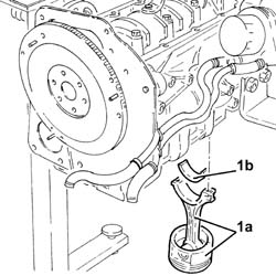
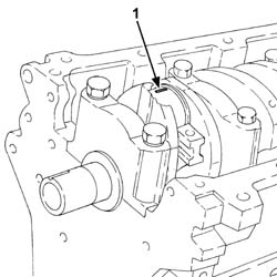
Rotate the crankshaft so that the crankpins are accessible.
1. Fit the calibrated wire (plastigage) for measuring the crankpin clearance.
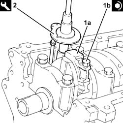
1. Place the bearing cap (1a), complete with half-bearing, back in its housing and secure it tightening the nuts (1b) to the recommended torque.
The references on the connecting rod cap and the big end should be on the same side.
| Fastening | Component | Ø | Value (daNm) | |
|---|---|---|---|---|
| 1b | Bolt | CONNECTING ROD CAPS | M9 | 2.4 ÷ 2.6 +60? |
2. Use the tool for the angular tightening of the connecting rod cap bolts.
| Description | Code | |
|---|---|---|
| 2 | Torque wrench | 1.860.942.000 |
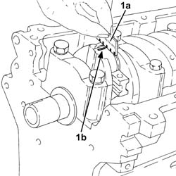
1. Remove the bearing cap fitted previously and, using a suitable graduated measuring instrument (1a), measure the clearance shown by the compression of the calibrated wire (1b).
arry out the clearance measurement operation for all the pins, taking care to proceed one pin at a time.
| Measurement | Value | ||
|---|---|---|---|
| Crankpin/half-bearnig clearance (mm) | 0.030 ÷ 0.056 |
If the figure measured is outside of the tolerance, replace the connecting rod half-bearings with ones of the appropriate size and category.
1. Place the connecting rod caps (1a) complete with half-bearings in their housings and secure them tightening the bolts (1b) to the recommended torque.
The references on the connecting rod cap and the big end should be on the same side.
| Fastening | Component | Ø | Value (daNm) | |
|---|---|---|---|---|
| 1b | Bolt | CONNECTING ROD CAPS | M9 | 2.4 ÷ 2.6 +60? |
2. Use the tool for the angular tightening of the connecting rod cap bolts.
| Description | Code | |
|---|---|---|
| 2 | Torque wrench | 1.860.942.000 |
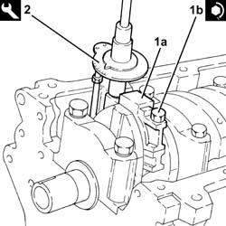
Clean any sealant residues from the mating surfaces between the engine oil sump and the engine block.
Apply silicon sealant to the entire perimeter of the crankcase sump.
1. Position the sump on the crankcase.
2. Tighten the front and rear bolts (2a) fixing the crankcase sump to the recommended torque using the tool (2b).
| Fastening | Component | Ø | Value (daNm) | |
|---|---|---|---|---|
| 2a | Front and rear bolts | OIL SUMP | M6 | (Engine crankcase side) 0.8 - 1.0 |
| Description | Code | |
|---|---|---|
| 2b | Spanner | 1.860.833.001 |
3. Tighten the side bolts (3a) fixing the crankcase sump to the recommended torque using the tool (3b).
| Fastening | Component | Ø | Value (daNm) | |
|---|---|---|---|---|
| 3a | Side bolts | OIL SUMP | M8 | (Engine crankcase side) 2.3 - 2.8 |
| Description | Code | |
|---|---|---|
| 3b | Spanner | 1.860.834.001 |
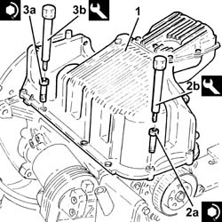
Tighten the engine oil drain plug to the recommended torque.
| Fastening | Component | Ø | Value (daNm) | |
|---|---|---|---|---|
| ENGINE OIL DRAIN PLUG | M18 | (Crankcase sump side) 1.8 - 2.2 |
Removing
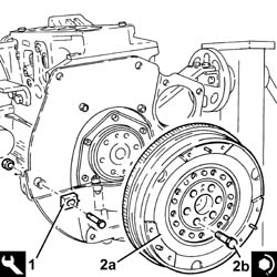
1. Fit the flywheel lock.
| Description | Code | |
|---|---|---|
| 1 | Counter-torque | 1.860.846.001 |
2. Undo the bolts (2a) and remove the engine flywheel (2b).
The bolts fixing the flywheel have been treated with a special locking compound; therefore they should be replaced each time they are removed.
Remove the flywheel lock.
| Description | Code | |
|---|---|---|
| Counter-torque | 1.860.846.001 |
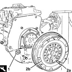
1. Undo the bolts (1a) and remove the flywheel guard (1b).
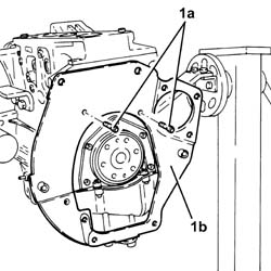
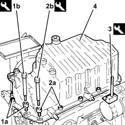
1. Undo the front and rear bolts (1a) fixing the crankcase sump using the tool (1b).
| Description | Code | |
|---|---|---|
| 1b | Spanner | 1.860.833.001 |
2. Undo the side bolts (2a) fixing the crankcase sump using the tool (2b).
| Description | Code | |
|---|---|---|
| 2b | Spanner | 1.860.834.001 |
3. Cut the crankcase sump sealant using the tool.
| Description | Code | |
|---|---|---|
| 3 | Blade | 1.870.718.000 |
4. Remove the crankcase sump.
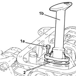
1. Undo the bolts (1a) and remove the engine oil intake duct (1b).
2. Remove the gasket.
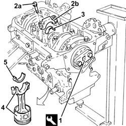
1. Fit the tool.
| Description | Code | |
|---|---|---|
| 1 | Flange | 1.820.618.000 |
Rotate the crankshaft using the tool fitted previously until the cylinder concerned is at B.D.C.
2. Undo the bolts (2a) and remove the connecting rod cap (2b).
3. Remove the lower connecting rod half-bearing.
4. Remove the connecting rod-piston assembly.
5. Remove the upper connecting rod half-bearing.
Carry out the same operations to remove the pistons and connecting rods for the remaining cylinders.
Refitting
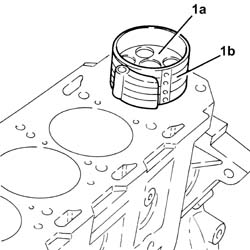
1. Place the piston and connecting rod assembly (1a) in its housing complete with half-bearing using a suitable tool (1b).
For the selection of the connecting rod half-bearings, follow the procedure described previously for the main journal half-bearings.
The piston-connecting rod assemblies should be fitted in the cylinder block/crankcase so that the drain on the piston skirt is aligned with the oil jet on the engine block.
Carry out the same operations to fit the pistons and connecting rods for the remaining cylinders.
1. Test the crankpin clearance by applying plastigage to measure crankpin installation clearance.
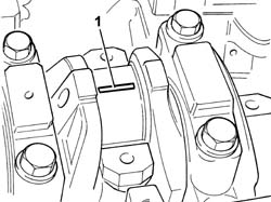
Place the connecting rod caps with half-bearings in their seats.
Fit the connecting rods so that the number stamped on each rod faces towardt he same side as the number stamped on the big end (inlet side).
1. Tighten the bolts (1a) to torque, using the angular tightening tool (1b).
| Fastening | Component | Ø | Value (daNm) | |
|---|---|---|---|---|
| 1a |
| Description | Code | |
|---|---|---|
| 1b | Torque wrench | 1.860.942.000 |
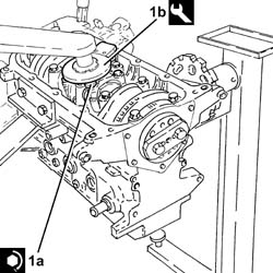
Undo the nuts and remove the connecting rod caps with the half-bearings fitted previously.
1. Use an appropriate graduated measuring tool (1a) to measure the clearance indicated by the plastigage (1b).
| Measurement | Value | ||
|---|---|---|---|
| 1b | Clearance between connectring rod bearings - crankpins (mm) | 0.016 ÷ 0.070 |
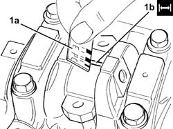
If the value measured is not within the recommended figures, replace the connecting rod bearings.
Carry out this test on all the crankpins, one at a time, without ever turning the crankshaft.
Fit the connecting rod cap complete with half-bearing and secure it without tightening the bolts.
Fit the connecting rods so that the number stamped on each rod faces towardt he same side as the number stamped on the big end (inlet side).
1. Tighten the connecting rod cap bolts (1a) to the recommended torque using the angular tightening tool (1b).
| Fastening | Component | Ø | Value (daNm) | |
|---|---|---|---|---|
| 1a |
| Description | Code | |
|---|---|---|
| 1b | Torque wrench | 1.860.942.000 |
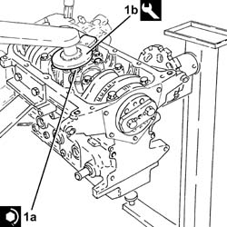
Remove the tool.
| Description | Code | |
|---|---|---|
| Flange | 1.820.618.000 |
Position the engine oil intake duct complete with gasket in its housing and secure it using the bolts.
Apply silicon sealant to the entire perimeter of the crankcase sump.
1. Place the crankcase sump in its housing.
2. Tighten the side bolts (2a) fixing the crankcase sump to the recommended torque using the tool (2b).
| Fastening | Component | Ø | Value (daNm) | |
|---|---|---|---|---|
| 2a |
| Description | Code | |
|---|---|---|
| 2b | Spanner | 1.860.833.001 |
3. Tighten the front and rear bolts (3a) fixing the crankcase sump to the recommended torque using the tool (3b).
| Fastening | Component | Ø | Value (daNm) | |
|---|---|---|---|---|
| 3a |
| Description | Code | |
|---|---|---|
| 3b | Spanner | 1.860.834.001 |
Place the rear flywheel guard in its housing and secure it using the bolts.
1. Fit the flywheel lock.
| Description | Code | |
|---|---|---|
| 1 | Counter-torque | 1.860.846.001 |
2. Place the flywheel (2a) in its housing and secure it by tightening the new bolts (2b) pretreated with sealant to the recommended torque.
| Fastening | Component | Ø | Value (daNm) | |
|---|---|---|---|---|
| 2b |
Use the tool for the angular tightening of the flywheel fixing bolts.
| Description | Code | |
|---|---|---|
| Torque wrench | 1.860.942.000 |
Remove the flywheel lock.
| Description | Code | |
|---|---|---|
| Counter-torque | 1.860.846.001 |
Removing
Rotate the engine through 180° on the overhaul stand.
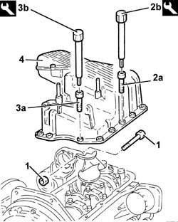
1. Undo the bolt connecting the crankcase sump to the intermediate shaft mount.
2. Undo the front and rear bolts (2a) fixing the crankcase sump using the tool (2b).
| Description | Code | |
|---|---|---|
| 2b | Spanner | 1.822.145.000 |
3. Undo the side bolts (3a) fixing the crankcase sump using the tool (3b).
| Description | Code | |
|---|---|---|
| 3b | Spanner | 1.822.144.000 |
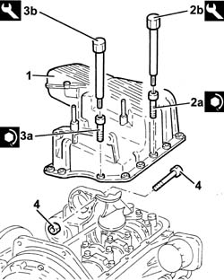
4. Remove the crankcase sump.
To release the crankcase sump, tap it gently using a wooden or resin hammer, then use a screwdriver for leverage in the projections at the sides of the sump.
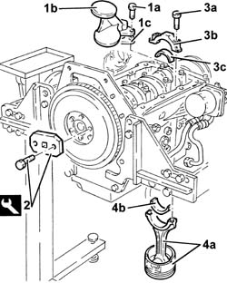
1. Undo the fixing bolts (1a) and remove the intake duct (1b) and the gasket (1c).
2. Fit the tool.
| Description | Code | |
|---|---|---|
| 2 | Flange | 1.820.618.000 |
Rotate the crankshaft using the tool fitted previously until cylinders 1 and 4 are at B.D.C.
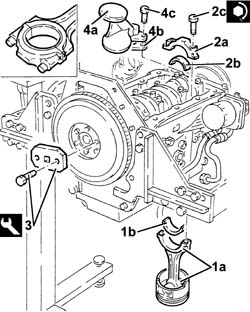
3. Undo the bolts (3a) and remove the connecting rod caps (3b) complete with half-bearings (3c) for cylinders 1 and 4.
4. Remove the cylinder 1 and 4 piston-connecting rod assemblies (4a) complete with half-bearings (4b)
Work in the same way to remove the piston/connecting rod assemblies for cylinders 2 and 3.
Refitting
Rotate the crankshaft until cylinders no.1 and 4 are at B.D.C.
The connecting rod half-bearings are selected as described below
1004E20 MOTORE - Scomp. e Ricomp. a seguito Op. 1004E10 - Lavaggio e controllo parti smontate - Riattacco testa cilindri e coppa olio - Non comprende interventi su testa cilindri e gruppo organi ausiliari
1. Remove the cylinder 1 and 4 piston-connecting rod assemblies (1a) complete with half-bearings (1b)
2. Place the connecting rod caps (2a) in their seats complete with half-bearings (2b) and secure them by tightening the bolts (2c) to the recommended torque.
Fit the connecting rods so that the number stamped on each rod faces towardt he same side as the number stamped on the big end.
| Fastening | Component | Ø | Value (daNm) | |
|---|---|---|---|---|
| 2c |
Use the angle wrench to tighten the connecting rod cap bolts through the specified angle.
| Description | Code | |
|---|---|---|
| Torque wrench | 1.860.942.000 |
Proceed in the same way to fit the 2nd and 3rd cylinder connecting rod assemblies.
3. Remove the tool.
| Description | Code | |
|---|---|---|
| 3 | Flange | 1.820.618.000 |
4. Fit the intake duct (4a) complete with gasket (4b) and secure it using the bolts (4c).
Apply silicon sealant to the entire perimeter of the crankcase sump.
1. Fit the crankcase sump.
2. Tighten the front and rear bolts (2a) fixing the crankcase sump to the recommended torque using the tool (2b).
| Fastening | Component | Ø | Value (daNm) | |
|---|---|---|---|---|
| 2a |
| Description | Code | |
|---|---|---|
| 2b | Spanner | 1.822.145.000 |
3. Tighten the side bolts (3a) fixing the crankcase sump to the recommended torque using the tool (3b).
| Fastening | Component | Ø | Value (daNm) | |
|---|---|---|---|---|
| 3a |
| Description | Code | |
|---|---|---|
| 3b | Spanner | 1.822.144.000 |
4. Tighten the oil sump bolt to the intermediate shaft mount.
Rotate the engine through 180° on the overhaul stand.
Parts & tools for this job Staging For 2003 Alfa Romeo GT
- PARTEngine gasket setSearch: Alfa Romeo GT 2003 engine gasket set
- TOOLTorque wrenchSearch: 3/8 inch torque wrench
- TOOLFeeler gauge setSearch: feeler gauge set
Links open Amazon search results in a new tab. As an Amazon Associate I earn from qualifying purchases.