
E3510 Car radio (3 door version)
- Make
- Alfa Romeo
- Model
- 147 Factory Service Manual
- Year
- 2000–2002
- Section
- Radio accessories › E3510 Car radio (3 door version)
E3510 Car radio (3 door version)
Description
The vehicle has a radio system comprising:
- radio (there are different versions)
- front loudspeakers (separate woofers and tweeters) located in the doors;
- rear loudspeakers (separate woofers and tweeters) located in the rear side panel;
- radio supply cables
- leads connecting the radio to the speakers;
- fishpole antenna with base mounted in the rear of the roof, coaxial cable and supply cable for aerial amplifier.
A radio with cassette player (CC) is fitted in the basic version.
It is also possible to install a radio with compact disc (CD) player.
If an integrated radio-telephone-navigator is used, the radio is incorporated in the unit.
The radio is prepared to control the multiple CD-CHANGER module - with 10 discs - located in the boot, on the right.
Note
if the system is prepared for the cellular 'phone Wiring diagram E3580 MOBILE TELEPHONE ARRANGEMENT or radiotelephone Wiring diagram E3570 INTEGRATED RADIO PHONE , the aerial is bi-functional (radio /GSM); if the navigator is also installed Wiring diagram E4090 NAVIGATOR , the aerial has three functions (radio/GSM/GPS).
Á
When the new radio is fitted on a vehicle, the connection is made with the Body Computer which asks for the radio code: this code, supplied by the radio manufacturer, is entered using the numerical keys, the Body Computer memorises this code and checks it whenever the radio is switched on.
The radio commands displayed on the radio display are repeated on the instrument panel ('HIGH' version).
Some versions have a set of buttons on the steering wheel: these make is possible to 'duplicate' some commands which are acquired in the same way by the radio.
The radio also manages the volume control linked to the vehicle speed: there is an increase and decrease in volume in accordance with the vehicle speed: this information reaches the radio node via the CAN.
For more details Characteristic of working principle 5570 Accessories .
It is also possible to install a sophisticated Bose Hi Fi system equipped with specific high fidelity loudspeakers with external amplifier. Wiring diagram E3510 CAR RADIO .
The radio has an anti-theft system made by connecting the radio on the CAN network to the Body Computer.
The radio receives the vehicle ignition signal via the CAN network, and is controlled in accordance with the following logic:
- if the radio is on and the car is switched off, so is the radio;
- if the car is switched on and the radio had been on previously, the radio stays on;
- if the car is switched on and the radio had been off previously, the radio stays off;
- if the radio is left on with the ignition off, it is automatically switched off after 20 minutes;
The radio is a node on the CAN network through which it exchanges information with the Body Computer and the other electronic units.
Description of operation
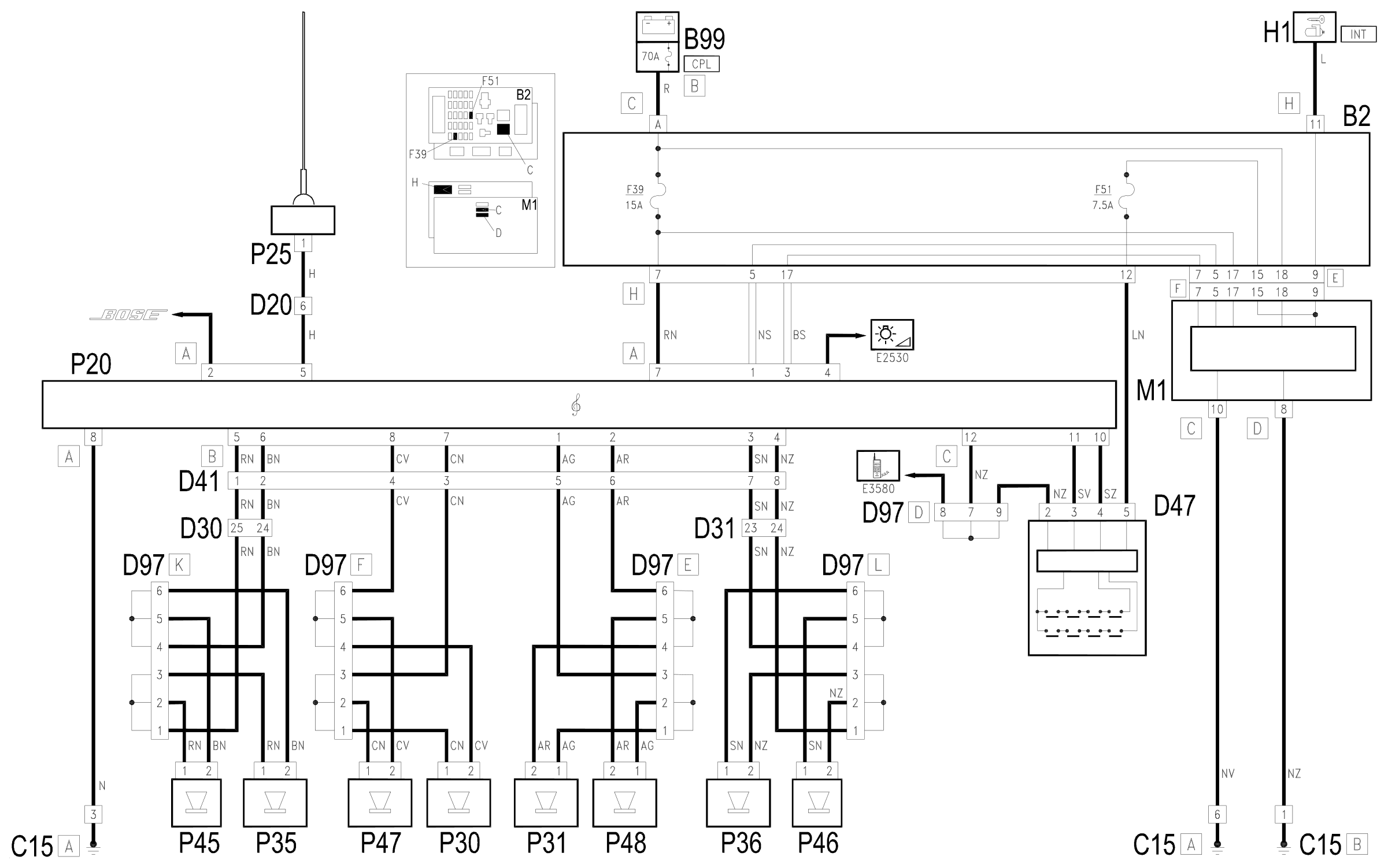
The radio P20 is supplied directly (7 of connector A) from the battery via the line of fuse F39 of the unit under the dashboard B1 and the maxifuse CPL of B99.
The supply to the side lights on reaches pin 4 of connector A Wiring diagram E2530 INSTRUMENT LIGHTING .
Pins 1 and 3 of connector A receive the CAN line with which the radio P20 is connected to the Body Computer M1 and the other nodes of the system.
Pin 8 of connector A is earthed.
The aerial P25 is supplied from pin 5 of connector A. The aerial is connected to the radio also via the specific coaxial cable.
Connector B sends out cables carrying signals to the speakers:
- pins 5 and 6 to left front loudspeakers P35 and P45,
- pins 3 and 4 to the right front loudspeakers P36 and P46,
- pins 7 and 8 to left rear loudspeakers P30 and P47,
- pins 1 and 2 to right rear loudspeakers P31 and P48,
Pins 10 and 11 of connector C are connected to the radio controls on the steering wheel: the connection is via the clock spring D47; the device which controls the control buttons receives a supply controlled by the ignition (INT) from the line protected by the fuse F51 of the unit under the dashboard B2, while the reference earth arrives from pin 12 of connector C of P20.
Wiring diagram
Components
| Code | Component | See |
|---|---|---|
| B01 | Engine compartment junction unit | description 5505A |
| B02 | Junction unit under dashboard | description 5505A |
| B98 | Supplementary fuse box | |
| B99 | Maxifuse box on battery | description 5530B |
| C15 | Facia earth, driver's side | |
| C65 | Bose system earth | |
| D20 | /Rear dashboard coupling | |
| D30 | Rear coupling for /front door. driver's side | |
| D31 | /Front passenger door. rear coupling | |
| D41 | Rear dashboard/ coupling for speakers | |
| D47 | Clock spring coupling | description 5580C |
| D68 | Bose system coupling | |
| D97 | Short circuiting coupling | |
| H01 | Ignition switch | description 5520A |
| M01 | Body computer | description 5505A |
| P20 | Car radio | |
| P25 | Aerial amplifier / feeder | |
| P30 | Left rear speaker | description 5570T |
| P31 | Right rear speaker | description 5570T |
| P35 | Speaker in driver's .front door | description 5570T |
| P36 | Speaker in front passenger door | description 5570T |
| P45 | Driver's front tweeter speaker | description 5570T |
| P46 | Front passenger side tweeter speaker | description 5570T |
| P47 | Rear left tweeter speaker | description 5570T |
| P48 | Rear right tweeter speaker | description 5570T |
| P49 | Bose system coupling | |
| P70 | Bose radio amplifier |
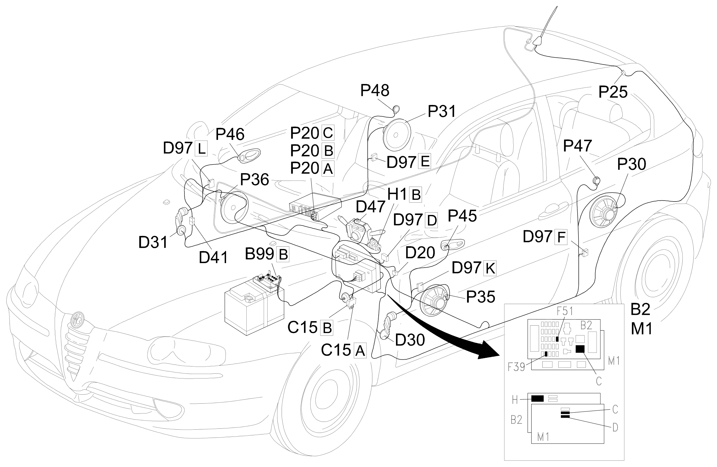
Component location
Parts & tools for this job Staging For 2000 Alfa Romeo 147
- TOOLTrim removal tool kitSearch: trim removal tool kit
- PARTTouch-up paintSearch: Alfa Romeo touch up paint
- PARTPanel clip assortmentSearch: Alfa Romeo panel clips assortment
Links open Amazon search results in a new tab. As an Amazon Associate I earn from qualifying purchases.