
E2530 Instrument lighting
- Make
- Alfa Romeo
- Model
- 147 Factory Service Manual
- Year
- 2000–2002
- Section
- Interior lighting › E2530 Instrument lighting
E2530 Instrument lighting
Description
The vehicle has numerous light sources for optimum lighting of the instruments and the controls.
Some of these are lit up when the ignition is ON (INT), others with the side lights on and on others the intensity varies according to a dimmer logic managed by the Body Computer.
The following controls light up when the ignition is turned ON:
- electric window switch on front door passenger side;
- controls for hazard warning lights, fog lights, rear fog lamp;
- controls for headlamp alignment, instrument lighting adjustment, milometer zeroing
- radio (basic version)
- switch unit on tunnel
The Body Computer manages the lighting of the following using the go ahead signals with the ignition ON (INT) and the side lights:
- cigar lighter/ashtray
- connection for radio phone
The Body Computer also manages the instrument panel and display light dimmer.
All the instruments are lit up with the ignition switched ON.
The light intensity can be adjusted to different levels, using an outside button, located in the panel to the side of the steering wheel: there are 11 different settings. (from 0 to 10)
The intensity level is set by pressing the 'MODE +' and 'MODE -' buttons and is shown on the instrument panel; the setting is also memorized and used later on.
Note
the light intensity cannot, however, be reduced to zero.
The light intensity level is also supplied, via the CAN, to the radio connectors (or the radio-phone-navigator) and the climate control system control unit to dim the backlighting of the displays: it ranges from maximum lighting (daytime) to dimmed lighting (nightime): the same logic also adjusts the control button lighting.
With the exception of the speedometer, the instrument panel lighting can be deactivated by operating the 'KM' button for a prolonged period (between 4 and 10s).
If there is a problem with one of the items not lit up (e.g. fuel reserve, engine coolant overheating, etc...) the entire panel is lit up.
On the 'BASIC' instrument panel: if the side lights are off, the intensity of the display lighting will always be 100%.
If the side lights are on, the graphics and the displays will be lit at the defined setting.
On the 'HIGH' instrument panel: the displays are lit up and can always be adjusted whether the side lights are off or on.
Description of operation
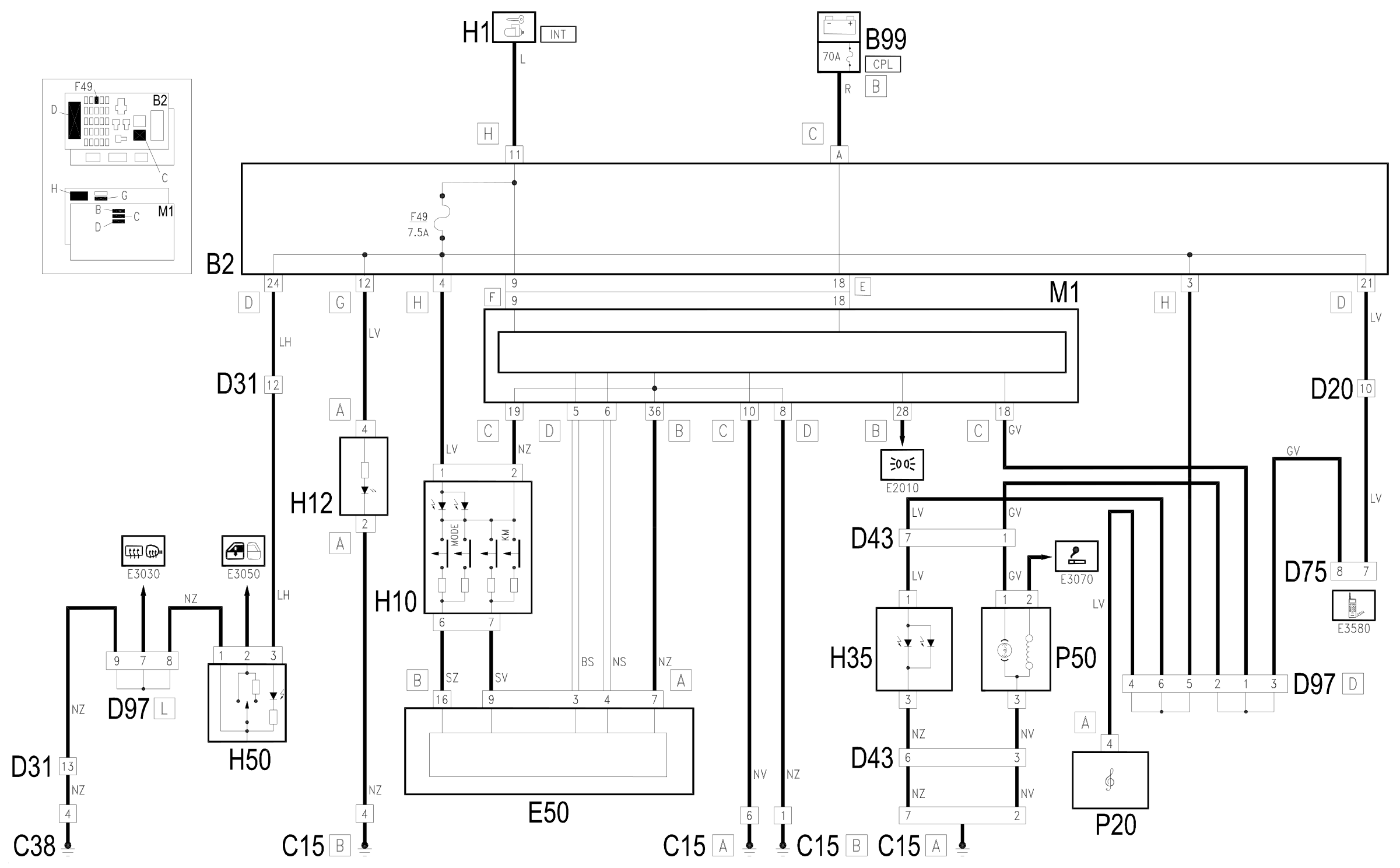
The supply line with the 'ignition ON' (INT) protected by the fuse F39 of the underdashboard control unit B2, provides the lighting for the electric windows switch in the front door, passenger side H50, the hazard warning lights, fog lights, rear fog lamp H12, headlamp alignment, instrument panel light adjustment, milometer zeroing H10, connector for preparation for the telephone D75 and lastly the switch unit on the tunnel H35 in addition to the radio P20 (BASIC version - without display).
The supply with the side lights on is, on the other hand, provided by the Body Computer M1 pin 18 of connector C to the cigar lighter P50 and to the connector for the preparation for the telephone D75.
The 'MODE' and 'KM' controls for the unit H10 are also supplied by the line (INT) protected by fuse F39 of control unit B2 and send the command to the instrument panel E50, pin 16 of connector B and pin 9 of connector A.
The Body Computer M1 is connected, via the CAN line, to the instrument panel E50 from which it receives the 'light intensity adjustment' signal which is transmitted to the radio connector (or the radio-phone-navigator) and to the climate control system control unit Wiring diagram E1050 CAN CONNECTION LINES .
Wiring diagram
Components
| Code | Component | See |
|---|---|---|
| B02 | Junction unit under dashboard | description 5505A |
| B99 | Maxifuse box on battery | description 5530B |
| C15 | Facia earth, driver's side | |
| C38 | Earth on centre tunnel | |
| D20 | /Rear dashboard coupling | |
| D31 | /Front passenger door. rear coupling | |
| D43 | Dashboard/centre console coupling | |
| D75 | Radio phone junction | |
| D97 | Short circuiting coupling | |
| E50 | Instrument panel | description 5560B |
| H01 | Ignition switch | description 5520A |
| H10 | Controls for headlamp alignment, instrument lighting adjustment, milometer zeroing | description 5560B |
| H12 | Hazard warning lights, fog lights, rear fog lamps control | description 5505A |
| H35 | Switches on tunnel | description 7040L |
| H50 | Electric window switch on .front passenger door | description 7005M |
| M01 | Body computer | description 5505A |
| P20 | Car radio | |
| P50 | Cigar lighter/current socket | description 7065C |
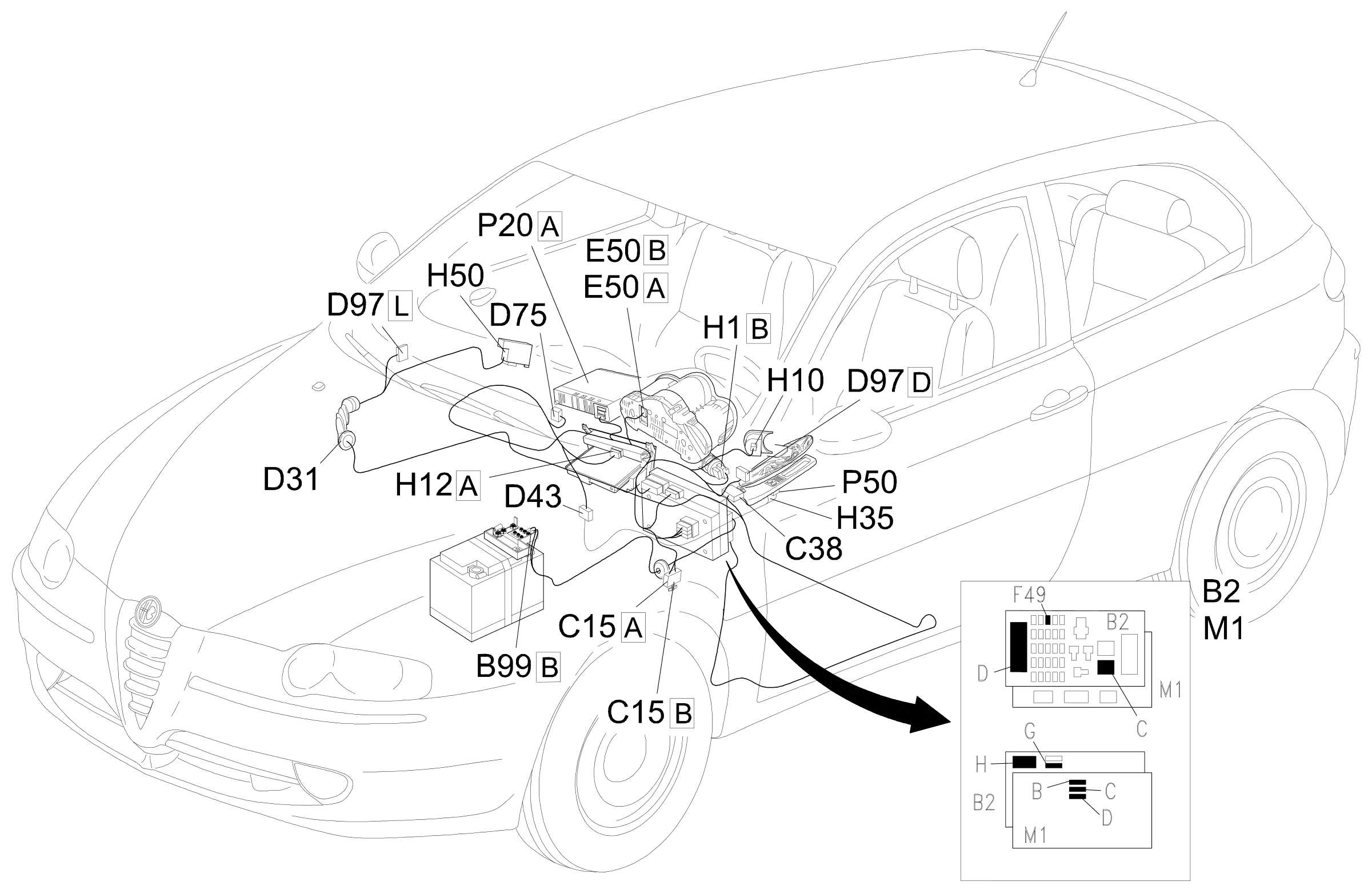
Component location
Parts & tools for this job Staging For 2000 Alfa Romeo 147
- PARTReplacement bulbsSearch: Alfa Romeo 147 2000 bulbs
- TOOLDigital multimeterSearch: automotive digital multimeter
Links open Amazon search results in a new tab. As an Amazon Associate I earn from qualifying purchases.