
E3580 Mobile telephone arrangement
- Make
- Alfa Romeo
- Model
- 147 Factory Service Manual
- Year
- 2000–2002
- Section
- Radio accessories › E3580 Mobile telephone arrangement
E3580 Mobile telephone arrangement
Description
The vehicle is also available, on request, with preparation for the installation of a mobile phone.
in the version with integrated radio-telephone-navigator, the telephone (GSM module and SIM-CARD reader) is integrated in it Wiring diagram E3570 INTEGRATED RADIO PHONE .
This system includes:
- connection for a portable telephone
- hands-free function through the radio speakers
- outside aerial
Note
a microphone to complete the hands-free function does not come with this equipment because it is provided in the telephone connection kit and should be positioned at will.
The connection for the telephone, located on the centre console, has all the supplies and signals needed for the operation of the telephone.
The fishpole antenna is mounted on the rear of the roof: it is a dual function aerial with two cables: one is the actual radio aerial, and one is the telephone cable, with dual reception band (GSM-ETACS at 900 Hz and D.C.S. at 1800 Hz).
The radio receives as input the audio signals from the telephone connection; the sound of the telephone always arrives at fixed volume, which is however adjustable in the radio's Menu function.
The operation of the telephone temporarily switches off the radio (MUTE function).
For more details Characteristic of working principle 5570 Accessories .
The telephone connection has two supplies; one direct and one with the ignition switched on: the above two lines are protected by two fuses in the unit under the dashboard; it also has a supply with the side lights on, to light up the telephone, if prepared.
Description of operation
The connection D75 receives the direct supply - pin 9 - from the battery via the line of fuse F39 of the unit under the dashboard B2.
It receives a supply controlled by the ignition (INT) - pin 7 - via the line of fuse F49, of the unit under the dashboard B2.
Pin 8 receives a supply with the side lights on, coming from the Body Computer M1, pin 18 of connector C: the telephone, if fitted is lit up like the other controls Wiring diagram E2530 INSTRUMENT LIGHTING .
Pin 10 of connector D75 is earthed, via the radio earth, pin 12 of connector C of P20.
Pins 4 and 5 supply the signal to the radio P20 - pins 7 and 8 of connector C, which then controls the speakers Wiring diagram E3510 CAR RADIO .
Pin 1 is also connected to the radio P20, pin 1 of connector C (MUTE function).
Wiring diagram
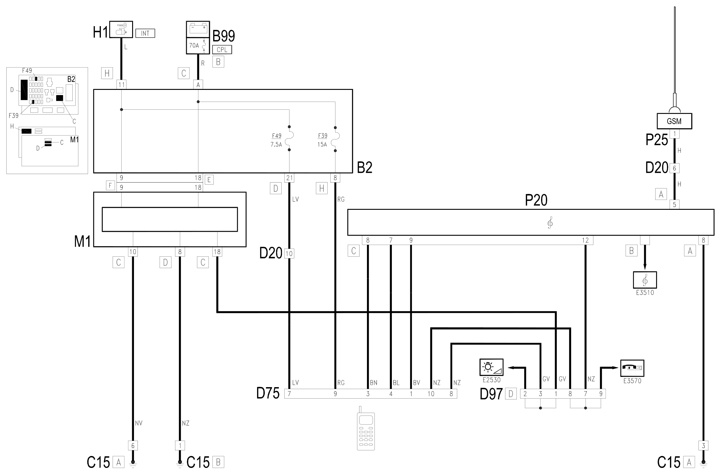
Components
| Code | Component | See |
|---|---|---|
| B02 | Junction unit under dashboard | description 5505A |
| B99 | Maxifuse box on battery | description 5530B |
| C15 | Facia earth, driver's side | |
| D20 | /Rear dashboard coupling | |
| D75 | Radio phone junction | |
| D97 | Short circuiting coupling | |
| H01 | Ignition switch | description 5520A |
| H05 | Stalk unit | description 5550A |
| M01 | Body computer | description 5505A |
| P20 | Car radio | |
| P25 | Aerial amplifier / feeder |
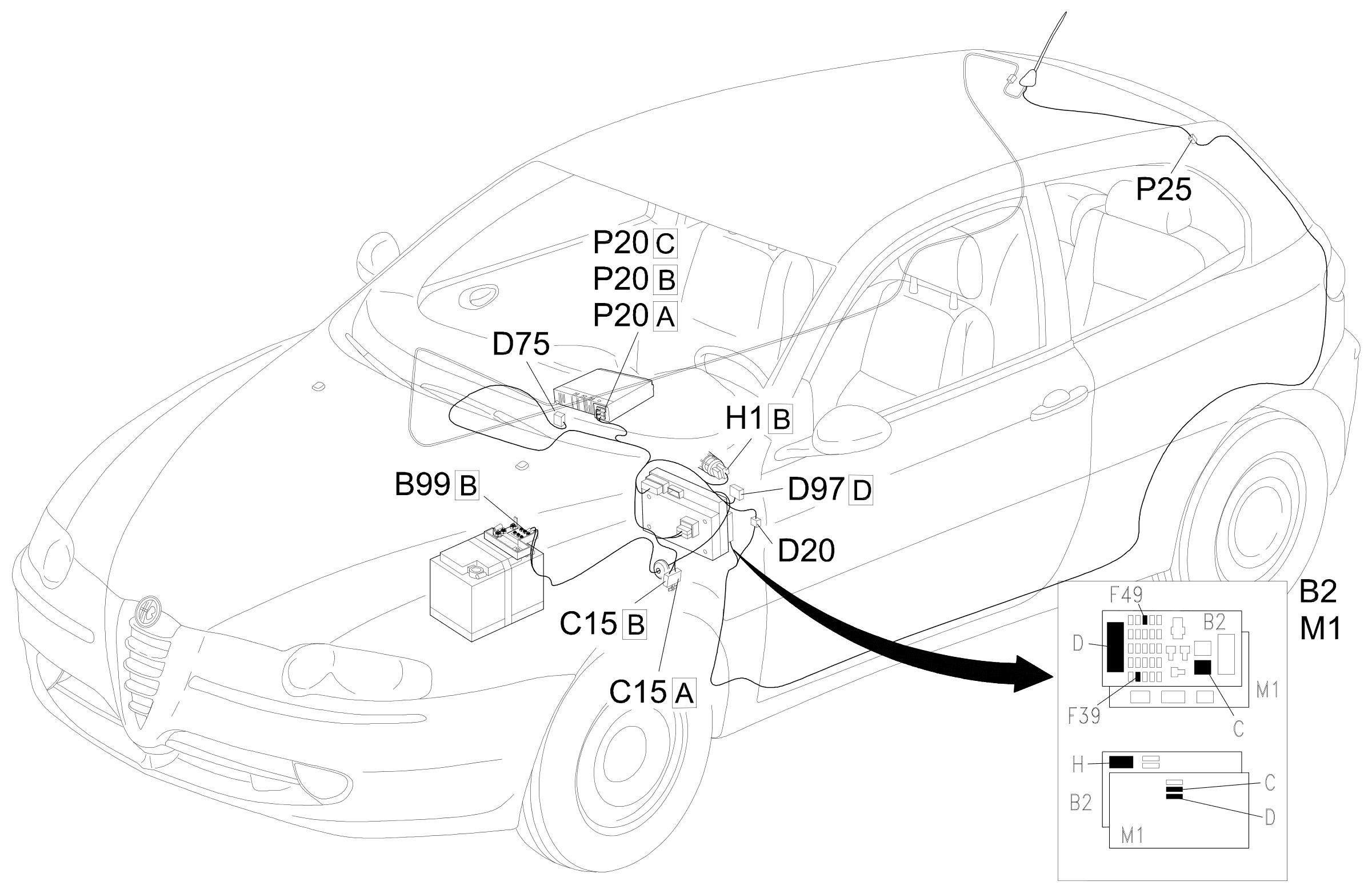
Component location
Parts & tools for this job Staging For 2000 Alfa Romeo 147
- TOOLDigital multimeterSearch: automotive digital multimeter
- PARTAssorted fuse kitSearch: car fuse assortment kit
- TOOLWire crimper and connector kitSearch: wire crimper connector kit
Links open Amazon search results in a new tab. As an Amazon Associate I earn from qualifying purchases.