Workshop Manuals Factory service & repair Land Rover
01 Range Rover Workshop Manual02 Range Rover Workshop Manual - Volume 103 04 05 06 01 - INTRODUCTION07 08 09 04 - GENERAL SPECIFICATION DATA10 11 12 05 - ENGINE TUNING DATA13 14 15 16 06 - TORQUE VALUES17 18 19 20 07 - GENERAL FITTING REMINDERS21 22 23 24 09 - LUBRICANTS, FLUIDS AND CAPACITIES25 26 27 28 29 10 - MAINTENANCE30 31 32 33 34 35 12 - ENGINE - BMW DIESEL36 37 38 39 12 - ENGINE - LAND ROVER V840 41 42 43 17 - EMISSION CONTROL44 45 46 47 19 - FUEL SYSTEM - BMW DIESEL48 49 50 19 - FUEL SYSTEM - LAND ROVER V851 52 53 54 19 - FUEL SYSTEM - CRUISE CONTROL55 56 57 58 26 - COOLING SYSTEM - BMW DIESEL59 60 61 62 26 - COOLING SYSTEM - LAND ROVER V863 64 65 66 30 - MANIFOLD AND EXHAUST SYSTEM67 68 69 70 33 - CLUTCH71 72 73 37 - MANUAL GEARBOX - R380 GEARBOX74 75 76 Range Rover Workshop Manual - Volume 277 78 79 80 41 - TRANSFER BOX81 82 83 84 85 86 87 44 - AUTOMATIC GEARBOX - ZF AUTO88 89 90 91 47 - PROPELLER SHAFTS92 93 94 51 - REAR AXLE AND FINAL DRIVE95 96 97 54 - FRONT AXLE AND FINAL DRIVE98 99 100 101 57 - STEERING102 103 104 105 60 - FRONT SUSPENSION - ELECTRONIC AIR SUSPENSION106 107 108 109 110 64 - REAR SUSPENSION - ELECTRONIC AIR SUSPENSION111 112 113 114 70 - BRAKES - ABS115 116 117 75 - SUPPLEMENTARY RESTRAINT SYSTEM118 119 120 121 122 123 76 - CHASSIS AND BODY124 125 126 127 128 129 77 - PANEL REPAIRS130 131 132 133 78 - SEATS134 135 136 137 80 - HEATING AND VENTILATION138 139 140 141 82 - AIR CONDITIONING142 143 144 145 84 - WIPERS AND WASHERS146 147 148 86 - ELECTRICAL149 150 151 152 153 154 87 - NAVIGATION SYSTEM155 156 157 158 159 88 - INSTRUMENTS
Land Rover Range Rover P38117 · 75 - SUPPLEMENTARY RESTRAINT SYSTEM
117 · Body & interior

SRS HARNESS - DISTRIBUTED SYSTEM (page 5 of 5)

Make
Land Rover
Model
Range Rover P38
Section
REPAIR
75 - SUPPLEMENTARY RESTRAINT SYSTEMSRS HARNESS - DISTRIBUTED SYSTEM · page 5 of 5
background image

SUPPLEMENTARY RESTRAINT SYSTEM

7

REPAIR

30. Disconnect driver’s air bag module connector.

Release connector and harness from clips.

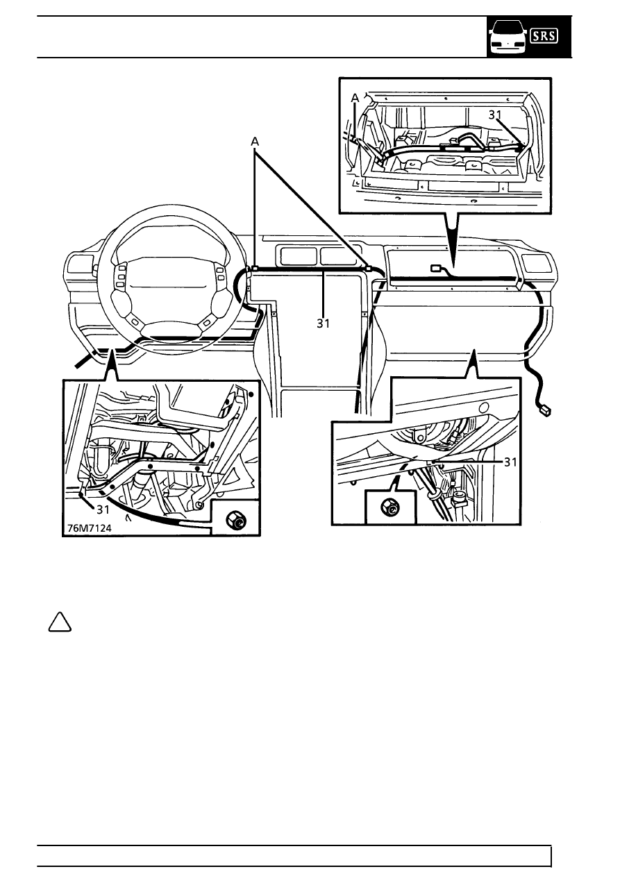
31. Release 13 clips securing SRS harness to fascia

frame.

NOTE: Due to restricted access, two outer
clips ’A’ securing harness above heater
unit may have to be cut. Ensure that

location holes are clear. Collect loose ends of
clips.

32. Release 3 clips securing fascia harness trunking

to passenger side fascia frame.

33. Remove nut securing lower end of each blower

assembly to fascia frame.

34. Route crash sensor ends of harness into

passenger air bag module space.

35. Feed SRS DCU connector into passenger air

bag module space.

36. Remove harness.

Refit

37. Position harness in passenger air bag module

space. Feed SRS DCU connector between
heater and fascia frame.

38. Route harness along transmission tunnel.

Secure harness clips.

39. Connect multiplug to DCU.
40. Fit sound deadener pad to transmission tunnel.
41. Route crash sensor ends of harness correctly

around fascia frame and behind blower
assemblies.

42. Secure harness clips to fascia frame.
43. Position fascia harness trunking. Secure with

clips.

44. Secure blower assemblies to fascia frame with

nuts.

45. Connect drivers air bag module, secure

multiplug and harness to trunking.

46. Connect SRS multiplug to instrument pack.

Parts & tools for this job Staging For Land Rover Range Rover

Links open Amazon search results in a new tab. As an Amazon Associate I earn from qualifying purchases.