
FRONT DIFFERENTIAL (page 3 of 4)
- Make
- Land Rover
- Model
- Range Rover L322 Range Rover Service Procedures
FRONT DIFFERENTIAL
REPAIRS
54-11
15. Fit an M14 nut to ball pin, flush with end of pin.
16. Using LRT-57-036 separate ball pin from
steering arm. Remove M14 nut and release ball
pin from steering arm.
CAUTION: Ensure ball joint seal is not
damaged. A damaged seal will lead to
premature failure of the joint.
17. Position container to collect oil spillage.
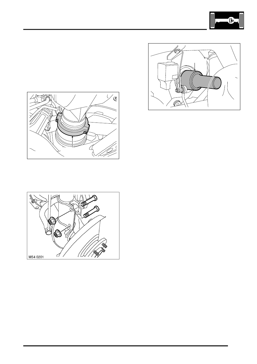
18. Fit LRT-54-026 to drive shaft inboard joint.
19. Using levers, release drive shaft from
differential.
20. Remove 2 nuts and bolts securing hub to
damper.
21. With assistance, remove hub and drive shaft
assembly.
22. Remove and discard shaft retaining clip.
23. Carefully remove oil seal from differential
housing, discard oil seal.
Refit
1. Clean oil seal register.
2. Use LRT-54-028 to fit new oil seal.
3. Clean end of drive shaft.
4. Lubricate lip of oil seal with differential oil.
LUBRICANTS AND SEALANTS,
Lubrication.
5. Fit new circlip to drive shaft.
6. Lightly lubricate splines and oil seal running
LUBRICANTS AND SEALANTS,
Lubrication.
7. With assistance, position hub and drive shaft
assembly. Carefully fit drive shaft through seal,
remove seal protector and push drive shaft fully
home to engage retaining clip.
8. Align hub to damper and tighten nuts and bolts
to 250 Nm (184 lbf.ft).
9. Clean ball joint tapers and taper seats.
10. Connect ball joint to steering arm, fit new nut
and tighten to 80 Nm (59 lbf.ft).
11. Connect tie rod to ball joint, fit nut and tighten to
80 Nm (59 lbf.ft).
12. Connect lower arm ball joint to hub, fit nut and
tighten to 80 Nm (59 lbf.ft).
13. Connect height sensor link to lower arm, fit nut
and tighten to 8 Nm (6 lbf.ft).
CAUTION: Ensure height sensor arm is
pointing outwards.
14. Clean ABS sensor, smear sensor with an anti-
seize grease and fit sensor to hub.
LUBRICANTS AND SEALANTS,
Lubrication.
15. Fit Allen screw securing ABS sensor and
tighten to 8 Nm (6 lbf.ft).
16. Secure sensor lead to damper.
17. Fit front brake disc.
M47 0414
LRT-54-026
M54 0181
LRT-54-028
Parts & tools for this job Staging For Land Rover Range Rover
- TOOLTorque wrenchSearch: 3/8 inch torque wrench
- TOOLSocket setSearch: socket set metric
- BOOKHaynes manualSearch: Haynes manual Land Rover Range Rover
Links open Amazon search results in a new tab. As an Amazon Associate I earn from qualifying purchases.