
Engine mounting - LH (page 4 of 4)
- Make
- Land Rover
- Model
- Range Rover L322 Range Rover Service Procedures
- Section
- REPAIRS
ENGINE - V8
12-2-50 REPAIRS
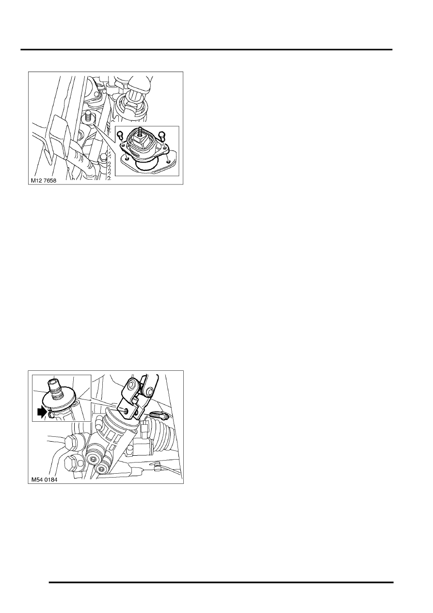
23. Remove 2 bolts securing LH engine mounting
to sub-frame and remove engine mounting,
discard bolts
NOTE: The LH engine mounting is removed
from under the LH front wheel arch through the
opening of the front sub-frame.
Refit
1. Clean engine mountings and mating faces.
2. Fit LH engine mounting to sub-frame and
tighten new bolts to 56 Nm (41 lbf.ft).
3. Lower engine onto engine mountings.
NOTE: Guide the fan cowl into position as the
engine is lowered.
4. Position PAS rack into front sub-frame and
using new Torx bolts and nuts tighten to 100
Nm (74 lbf.ft), then tighten a further 90
°
.
5. Connect intermediate steering column to PAS
rack and tighten securing clamp Torx bolt to 24
Nm (18 lbf.ft).
NOTE: Make sure that intermediate steering
column is correctly aligned to PAS rack.
6. Connect multiplug to PAS rack pinion sensor.
7. Connect track rod ends to steering arms, using
new nuts tighten to 55 Nm (41 lbf.ft).
8. Connect link to suspension height sensor and
tighten nut.
9. Fit front road wheels and tighten nuts to 140
Nm (103 lbf.ft).
10. Fit 2 nuts securing engine mountings to engine
mounting brackets and tighten to 100 Nm (74
lbf.ft).
11. Remove engine lifting chains.
12. Remove engine lifting bracket.
13. Fit fan cowl to radiator and fit securing scrivets.
14. Fit auxiliary cooling fan multiplug to fan cowl.
15. Fit screw securing fan cowl to radiator.
16. Fit undertray.
17. Fit differential air flow panel and tighten bolts to
45 Nm (33 lbf.ft).
18. Remove stands and lower front end of vehicle.
19. Connect air intake hose.
V8, REPAIRS, Hose - air flow meter to
throttle body.
20. Fit air intake plenum.
21. Connect battery earth lead.
Parts & tools for this job Staging For Land Rover Range Rover
- PARTEngine gasket setSearch: Land Rover Range Rover engine gasket set
- TOOLTorque wrenchSearch: 3/8 inch torque wrench
- TOOLFeeler gauge setSearch: feeler gauge set
Links open Amazon search results in a new tab. As an Amazon Associate I earn from qualifying purchases.