
Torque Converter (page 3 of 4)
- Make
- Land Rover
- Model
- Range Rover L322 Range Rover System Description and Operation
- Section
- Description
AUTOMATIC TRANSMISSION – ZF 5HP24
DESCRIPTION AND OPERATION 44-2-13
When the engine speed increases, the turbine speed also increases. The fluid leaving the inner row of the turbine
blades is rotated in an anti-clockwise direction due to the curve of the turbine and the shape of the blades. The fluid
is now flowing in the opposite direction to the engine rotation and therefore the impeller. If the fluid was allowed to hit
the impeller in this condition, it would have the effect of applying a brake to the impeller, eliminating the torque
multiplication effect. To prevent this, the stator is located between the impeller and the turbine.
Stator
The stator is located on the splined transmission input shaft via a freewheel clutch. The stator comprises a number of
blades which are aligned in an opposite direction to those of the impeller and turbine. The main function of the stator
is to redirect the returning from the turbine, changing its direction to that of the impeller.
The redirected fluid from the stator is directed at the inner row of blades of the impeller, assisting the engine in turning
the impeller. This sequence increases the force of the fluid emitted from the impeller and thereby increases the torque
multiplication effect of the torque converter.
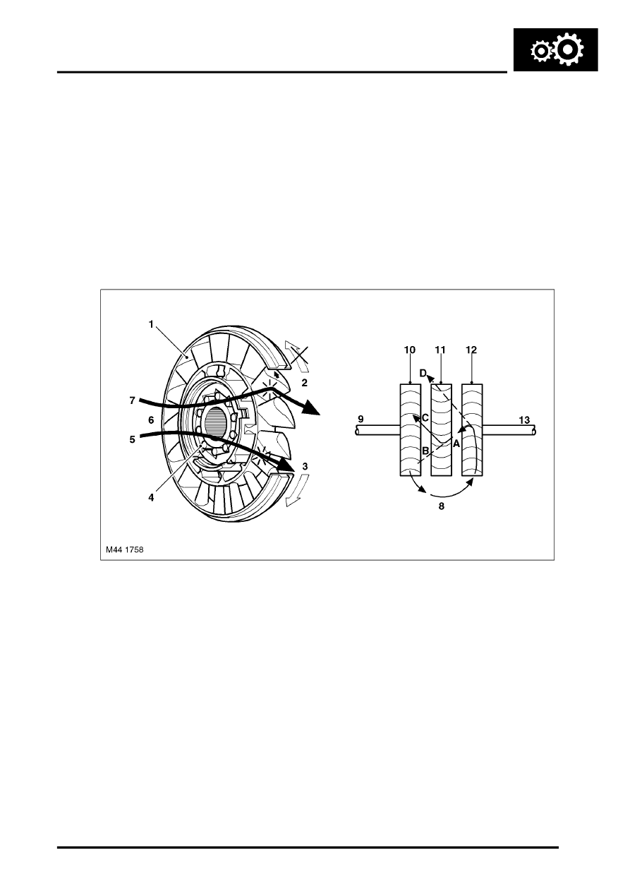
Stator Functions
Typical stator shown
1 Blades
2 Stator held – fluid flow redirected
3 Stator rotates freely
4 Roller clutch
5 Converter at coupling speed
6 Fluid flow from turbine
7 Converter multiplying
8 Fluid flow from impeller
9 Drive from engine
10 Impeller
11 Stator
12 Turbine
13 Output to transmission
Refer to the 'Stator Functions' illustration
Fluid emitted from the impeller acts on the turbine. If the turbine is rotating at a slower speed than the fluid from the
impeller, the fluid will be deflected by the turbine blades in the path 'A'. The fluid is directed at and deflected by the
stator blades from path 'B' to path 'C'. This ensures that the fluid is directed back to the pump in the optimum direction.
In this condition the sprag clutch is engaged and the force of the fluid on the stator blades assists the engine in rotating
the impeller
Parts & tools for this job Staging For Land Rover Range Rover
- PARTTransmission filter kitSearch: Land Rover Range Rover transmission filter kit
- FLUIDAutomatic transmission fluidSearch: Land Rover automatic transmission fluid
- TOOLFluid transfer pumpSearch: fluid transfer pump
Links open Amazon search results in a new tab. As an Amazon Associate I earn from qualifying purchases.